Honda Fit (GE8) LED Taillight and Rear Fog Light Retrofit
Introduction
This guide covers retrofitting JDM-style LED taillights and a working left-side rear fog light to a USDM/NA Honda Fit Sport (GE8, roughly 2009-2013). Several markets, including Taiwan, the UK, Germany, and China, sell the Fit/Jazz with LED tails that carry a left-hand-drive rear fog lamp: a single red light of brakelight-level intensity (about 21/23W) intended to make a vehicle visible in heavy fog, torrential rain, or a snow white-out. Because the USDM Sport already routes its combination-switch fog dial to the front fogs, the factory Base-model foglight switch, harness, and relay can be repurposed to drive the rear fog through the car's existing fuse/relay module. The job pairs a plug-and-play taillight swap with a modest amount of interior trim removal, a single wire run from the rear to the fuse box, one signal tap, and light soldering. Sourcing the correct OEM parts is the main hurdle. Adapted from a community writeup by Zalthras on FitFreak (https://www.fitfreak.net/forums/fit-interior-exterior-illumination/50088-diy-led-tails-w-rear-foglight-ge8-sport.html), including corrections from the follow-up discussion.
Reference
Tools Required
- Trim removal tools (e.g. KTC Panel Popper kit)
- Soldering gun, roughly 35W or higher, plus solder
- Wire stripper/cutter
- Crimper (a D-Sub crimper works for Molex pins)
- Heat gun or blow dryer for heatshrink
- Scissors
- Ratchet with 8mm and 14mm sockets
- Multimeter (for verifying the parking-light feed)
Parts Required
-
Right LED taillight 33500-TF0-J01 (or 33500-TF0-J51 for 2012 non-RS/Hybrid)
-
Left LED taillight with LHD rear fog 33550-TF0-G01 (or 33550-TF0-G51 for 2012 non-RS/Hybrid)
-
Base-model foglight switch 08V31-SMA-0M035
-
Base-model foglight switch harness 08V31-TK6-10030
-
Relay 39794-SDA-A05
-
7.5A fuse 38221-SNA-A31 (or 10A fuse 38221-SNA-A41)
-
Connector, 2P .090 F, 04321-SH2-307
-
Two pigtails (0.5) 04320-SP0-A00
-
Length of wire
-
2-pin .062 Molex connector pair
-
Heatshrink and/or electrical tape
-
Zip ties
Safety Warnings
- ⚠ Disconnect the negative battery terminal before working on any of the wiring to avoid shorts and blown fuses.
- ⚠ Use minimal force on the door sill and kick panels; the clips release easily and over-prying cracks the trim.
- ⚠ A rear fog is very bright and is meant only for genuine low-visibility conditions (dense fog, downpour, or white-out snow); leaving it on in normal driving dazzles following traffic and can be mistaken for a brake light.
Step-by-Step Instructions
1 Source the correct OEM parts

Gather the assemblies and fog-circuit hardware before starting. Only the driver-side unit carries the rear fog reflector, so order left assembly 33550-TF0-G01 (or 33550-TF0-G51 on the 2012 non-RS/Hybrid) together with right assembly 33500-TF0-J01 (or 33500-TF0-J51). For the fog wiring you also need Base-model foglight switch 08V31-SMA-0M035, Base foglight switch harness 08V31-TK6-10030, relay 39794-SDA-A05, a 7.5A fuse (38221-SNA-A31) or 10A fuse (38221-SNA-A41), connector 04321-SH2-307 (2P .090 F), and two pigtails 04320-SP0-A00. Add wire, heatshrink, a 2-pin .062 Molex pair, and zip ties. This install assumes a USDM/NA Sport, whose combination-switch dial already drives the front fogs, leaving the Base foglight accessory circuit free for rear-fog duty.
2 Install the LED taillight assemblies

Remove the factory taillights and mount the LED units. The listed OEM part numbers ship complete with their own bulbs and sockets, so the swap is plug-and-play. The LED bulb positions line up with the original USDM sockets, letting every factory connector reach without stretching any leads. At this point only the left assembly carries the rear fog element; its dedicated wiring is added later.
3 Strip the rear cargo trim
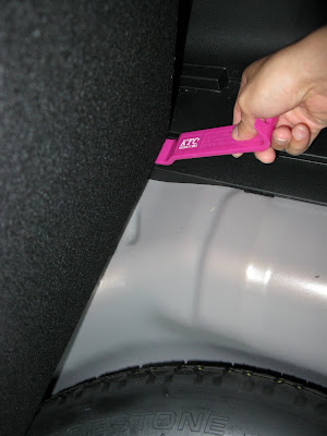
Work from the cargo bay to expose a path for the fog wire. Lift the spare-tire cover and pry the cargo floor up off its two clips; take care, since the center of the floor hinge is bonded to two glued foam blocks. Free the rear sill panel by prying its lower corners to release the corner hooks, then lifting to unhook the remaining tabs and clips. Pop the cargo-area lamp lens out from its front edge and unplug it. Finally remove the left cargo-area side panel: fold the rear seat down, ease the door seal away, drop the tie-down D-ring if fitted, release the clips, work the top edge loose starting at the door, and feed the seatbelt through.
4 Remove the driver-side trim to open a wire channel
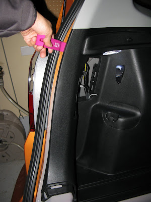
Continue the path up the driver's side toward the fuse box. Twist the plastic knob a quarter turn and drop the dashboard undercover. Peel the front door seal back, then release the kick panel by freeing its lower hook first and pulling it inward, holding the hood release out of the way as the panel comes off. Lift the front door sill trim gently to release its clips; it needs very little force, so avoid prying hard. Unhook its joining edge, then repeat for the rear door sill trim by popping or sliding it off its clip, and work the lower B-pillar trim loose. Together these panels open the channel that carries the wire from the cargo area up to the fuse module.
5 Route the single switched wire forward
Run one length of wire from the driver-side fuse-box area back to the rear fog. Only a single conductor is needed: the Base foglight accessory harness supplies a switched positive up front, while the fog's ground can be tapped to bare body metal at the rear. Feed the wire along the sill channel you just exposed, keep it clear of any moving parts, and leave enough slack at each end to reach the rear fog connector and the fuse module.
6 Disconnect the battery and mount the switch harness and relay
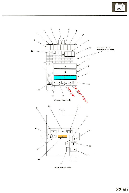
Disconnect the negative battery terminal before touching any wiring. Fit the Base-model foglight switch harness at the fuse/relay module (MICU). Skip the separate relay-bracket assembly called out in the Honda accessory instructions; instead, slide the relay carrier straight onto the MICU front-to-back until it snaps into place. The published Honda accessory document (handa-accessories 09fog.pdf, steps 33-62) describes the general harness routing, but the deviations in the following steps are what adapt it to a Sport.
7 Tap the control signal at pin 42 of connector C
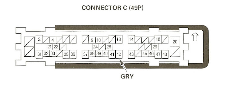
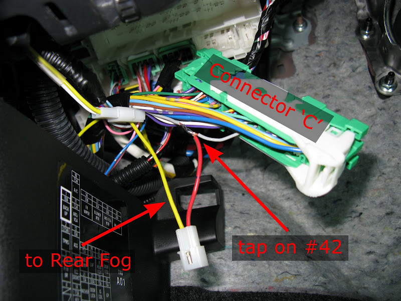
Establish the switched control feed. A Sport has no factory 2-pin fog connector to plug into, so the wire you ran from the rear must instead be spliced into pin 42 of the 'C' connector. That pin carries parking-light power from the parking-light relay, so joining the fog control here makes the rear fog live only when the parking or headlights are on. Cut the harness's original 2-pin connector off and terminate the joint with the 2-pin .062 Molex pair for a cleaner, serviceable connection; solder the splices and seal them with heatshrink.
8 Set up the fuse
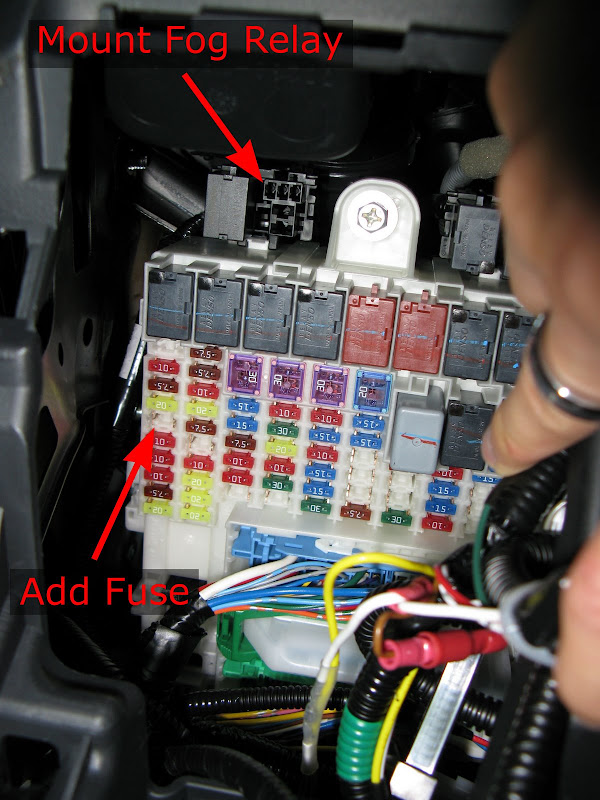
A single rear foglamp draws only about 2 amps, so the 20A fuse called for in the generic instructions is unnecessary. Reuse a 7.5A fuse and place it in position 4. The unused accessory-supply slot at position 15 is a convenient donor for that fuse. On a Base model that circuit feeds the front fog accessory; on the Sport it powers nothing from the factory, which makes it ideal for the rear fog.
9 Install the switch, reassemble, and test
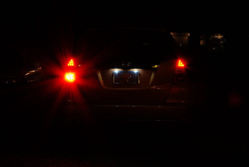
Seat the foglight switch into a blank in the switch panel and reconnect every plug at the MICU. Reconnect the battery. Switch the parking lights on and confirm the rear fog lights only while the switch is pressed, and that it goes out when the parking lights are turned off. Once the behavior checks out, zip-tie the loose wiring so nothing rattles or chafes, then reinstall the trim panels in the reverse order of removal.
Pro Tips
- 💡 Sharing the fog's power with the parking-light circuit means it cannot be left on by mistake: when you kill the parking lights the fog goes out, and the car's parking-light reminder chime backs that up.
- 💡 Because a single foglamp pulls only about 2A, a small 7.5A fuse is plenty; there is no need for the 20A the generic harness instructions specify.
- 💡 Only one wire has to be routed the length of the car, since the accessory harness supplies the switched positive and the rear fog can ground to nearby body metal.
- 💡 The 2012 non-RS/Hybrid LED tails are a direct swap into the 2009-2011 GE cars if you prefer the later lens styling.
- 💡 Connector 04321-SH2-307 is the same part used on many Honda taillight and interior-light circuits from 1990 on, so it is easy to source in small quantities.
Was this guide helpful?