Honda CR-Z JDM Reverse-Tilt Passenger Mirror Installation
Introduction
The reverse-tilt mirror is a Honda Access accessory sold only in the Japanese market that automatically angles the passenger-side door mirror downward whenever reverse gear is selected, giving a clear view of the curb and rear wheel while parking. Because it was never offered through US dealers, fitting it to a US-market CR-Z means adapting the Japanese add-on harness, whose door-connector pinout does not match the US wiring; left unchanged, both the power windows and the tilt module will fail to operate. Aside from re-arranging a handful of connector terminals, the remainder is essentially plug-and-play: mount the control module behind the passenger dash, add a fuse, dial in the desired tilt angle, and splice one wire into the reverse-lamp circuit. This guide applies to the Honda CR-Z. Right-hand-drive (JDM/EDM) cars that already run power-folding mirrors may find the tilt function plugs straight in, though the door harness can still need re-pinning. Adapted from a community writeup by ITEM9 on CRZ Forum (https://www.crzforum.com/threads/diy-jdm-reverse-tilt-mirror.9731/), including corrections from the follow-up discussion.
Reference
Tools Required
- Precision flathead screwdriver set (for releasing connector pins)
- Two small sewing needles or pins (for releasing the small pins)
- Phillips screwdriver
- 10mm socket
- 8mm socket
- Pliers
- Multimeter (helpful when adapting the harness on non-USDM cars)
Parts Required
-
Honda Access Reverse Interlocked Door Mirror kit (part number 08V08-SZT-000)
-
20A blade fuse (supplied with the kit)
Safety Warnings
- ⚠ Work slowly when depinning; a damaged connector or a terminal that will no longer seat can leave you a pin or wire short and stall the install, as several builders discovered.
- ⚠ Leave jumper switch number 4 OFF. It can drive the mirror past its mechanical limit and hold it bottomed out.
Step-by-Step Instructions
1 Separate and unlock the add-on door connectors

The Japanese add-on harness ends in two door connectors whose terminals are locked by an inner and outer housing. Before any pin can be freed, ease the two housing halves slightly apart so their side latches step up to the next detent. Small plastic claws on both the male and female bodies hold the halves together; one half is wrapped in foam, which can stay in place. Lift each claw with a fine flat screwdriver and shift it up. Do this on both connectors, and take care not to press them shut again while handling them. Everything that follows applies only to the add-on harness; leave the car's own door wiring untouched.
2 Relocate the three large power-window terminals

Tackle the power-window circuit first; its terminals are the large ones and release most easily. Above each pin on the mating face is a hole, so insert the precision flat screwdriver there to lift the retention tab away from the terminal, then draw the wire out while gently working it in and out so the tab does not bind. Re-seat the three terminals into their correct US positions: drop the large WHITE wire one socket lower into the empty position beneath it; move the large BROWN wire into the free socket beside the white wire's new home; and place the large YELLOW wire into the socket the brown wire just left. Push each terminal home until it clicks. If one stays loose, bend its plastic tab down a little so it catches again.
3 Correct the module ground pair

The tilt module only powers up once its ground is routed to the US pinout, which means exchanging two of the small terminals: the uppermost small GRAY wire trades sockets with the BLACK wire. These small terminals are far harder than the power-window ones because their release holes are tiny and hidden. Instead of levering the center of the tab as on the large pins, slide a needle into each bottom corner of the square hole, work both under the tab on either side of the terminal's metal catch, and wedge the tab clear. A single needle will not release it, so use two. Begin on the female connector, where the holes sit at the surface, before moving to the male side where the sockets are recessed.
4 Swap the horizontal and vertical tilt wires

In the Japanese harness the two mirror-axis control wires are transposed, so left as-is the mirror would swing side to side in reverse rather than tipping down. Exchange them: the remaining small striped GRAY wire changes places with the small striped PINK wire. The main colors match across both door connectors, with the stripe present on one side only. Use the same two-needle wedge method. These terminals sit in the lowest positions of the male connector and are the most awkward of all, while the female connector is easier because its release holes are not sunk into the body.
5 Reassemble and verify the modified harness

Repeat every pin move on both connectors at that end of the harness, then mate the harness back into itself and confirm each wire color lines up across the join. Once satisfied, press the connector halves back down into their fully locked detent. A correctly reworked harness now matches the US door pinout and is ready to install in the car.
6 Strip the passenger-side dash
Reach the module location and wiring runs by removing, in order: the passenger HVAC vent panel (6 clips); the trim panel above the glovebox (8 clips); the trim panel below the glovebox (4 clips plus the floor LED light connector); and the glovebox itself (2 Phillips screws, 4 8mm screws, 4 clips, and its light). Take off the passenger lower pillar garnish (2 clips). On the driver's side, remove the fuse-box cover (6 clips) and the under-dash trim panel (2 clips and 1 plastic thumbscrew).
7 Fit the 20A fuse
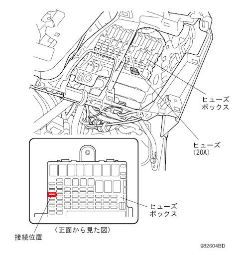
Insert the 20A fuse into position number 4 of the dash fuse box, which is the empty socket four rows down from the upper-left fuse.
8 Set the tilt angle on the module jumpers

A recessed bank of jumper switches sits beside the module's connector and sets how far the mirror drops; nudge them with a precision screwdriver. Maximum travel is 6.9 degrees, selected with the pattern ON-OFF-ON-OFF. If the mirror bottoms out at that angle for your seating position, back it off one step. Keep switch number 4 OFF in every combination, because enabling it can command more travel than the mirror can physically reach.
9 Mount the control module to the firewall stud

Fit the module onto its bracket, then mount the assembly to the passenger-side blower housing. Remove the upper 10mm nut on the blower assembly stud, slide the bracketed module onto the stud, and refit the nut. Hold the module vertical and counter-hold it as you tighten so it does not rotate out of position.
10 Connect the harness and tap the reverse feed

With the module mounted and the harness reworked, the rest is plug-and-play. Route and plug the passenger-side mirror harness into the module (the 16-pin black connector) and into the fuse-box connector, then make the single required splice: tap the module's trigger wire into the car's reverse-lamp signal wire so the mirror tilts the instant reverse is engaged. Reinstall the dash trim in reverse order and test by selecting reverse with the ignition on.
Pro Tips
- 💡 Release the small terminals by wedging a needle under each side of the retention tab rather than prying the middle up with a single tool; ITEM9 later noted this method is far easier on the white 23-pin door connectors and carries much less risk of wrecking a terminal.
- 💡 Start with the female connector, whose release holes sit flush, then move to the recessed male connector; a helper holding light tension on the wire makes the small pins come out more readily.
- 💡 For the maximum 6.9-degree drop use ON-OFF-ON-OFF, and reduce the angle only if the mirror bottoms out for your viewing position.
- 💡 RHD/EDM cars (UK, Europe): the tilt function itself may plug in and work, but the power windows can still need re-pinning. One UK owner found the body harness two wires short of the Japanese harness with some colors different, moved only the large pins, added the missing large pin, and substituted Sumitomo connectors to finish it.
- 💡 A multimeter helps identify constant-live and switched wires when adapting the harness to a market other than USDM.
Was this guide helpful?
