
Hardwiring a High-Flow Fuel Pump with a Dedicated Relay (Honda/Acura)
- You are working around gasoline and fuel vapors while soldering and making electrical connections. Should working near gasoline, its vapors, or electrical wiring be outside your comfort zone, have a professional do this job.
- Inspect the insulation of the new battery cable every couple of feet as you route it. A damaged section can cause a hidden short on an always-hot, high-current wire.
- Do not touch or bend a solder joint until it has cooled completely - a disturbed (cold) joint makes a poor, unreliable electrical connection.
- Always run a correctly sized fuse (25 A ATC here) in the new battery feed, installed close to the battery.
Introduction
High-flow aftermarket fuel pumps such as the Walbro 450 LPH draw far more current than the factory fuel pump circuit was designed to carry. This procedure hardwires the pump through a dedicated 40 A relay fed directly from the battery with 10 AWG cable, using the original fuel pump power and ground wires only as low-current relay trigger signals. The result is full battery voltage at the pump and reduced load on the factory harness and main relay. The writeup was performed on a 1999 Acura Integra GSR (DC2) ahead of a Walbro 450 LPH install, and the same approach applies to other Honda and Acura models of the era with model-specific wire colors. Every crimped joint is also soldered and double-layer heat shrunk for vibration resistance. Adapted from a community writeup by Destructive- on Honda-Tech (https://honda-tech.com/forums/forced-induction-16/official-how-hardwire-fuel-pump-3279999/), including corrections from the follow-up discussion.
Procedure
12 steps-
Step 1: Gather parts and tools
Lay out all materials before starting: 10 AWG lead and ground cable, a 10 AWG inline fuse holder, a 40 A automotive relay, OEM Honda spade connectors for the fuel pump plug (part no. 07692-0011000 - buy extras in case of a bad crimp), 12-10 AWG female spade connectors, a 3/8 in ring terminal, 25 A ATC fuses, fire-retardant wire conduit, heat shrink, electrical tape, and rosin flux. A high-wattage soldering station is important: 10 AWG wire sinks a lot of heat, and the author ran his iron at about 750 F to get solder flowing within roughly 5 seconds.
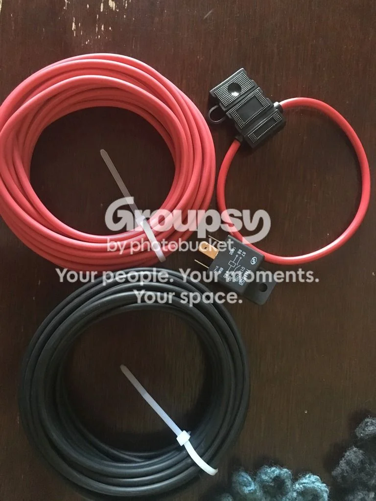
FIG. 2.1 -
Step 2: Remove interior trim for harness access
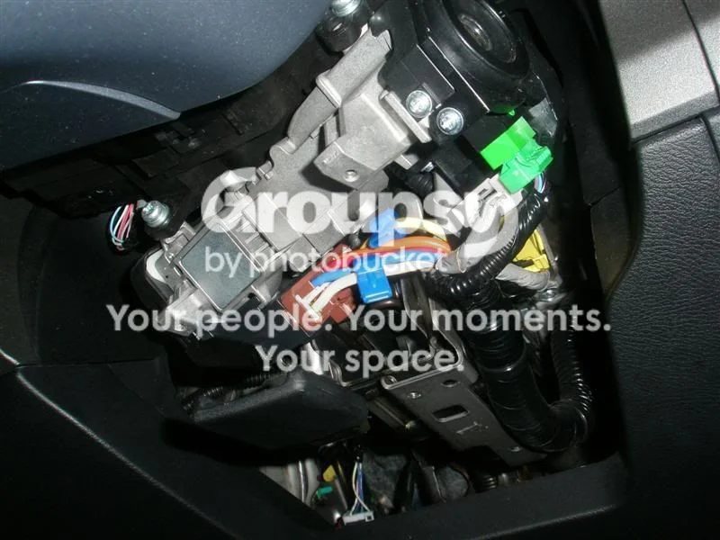
Remove the plastic kick panel covering the ECU, then pull the floor mat and carpet out of the way and remove the plastic trim holding the carpet. This exposes the area behind the passenger-side glove box and the path along the floor to the rear seat.
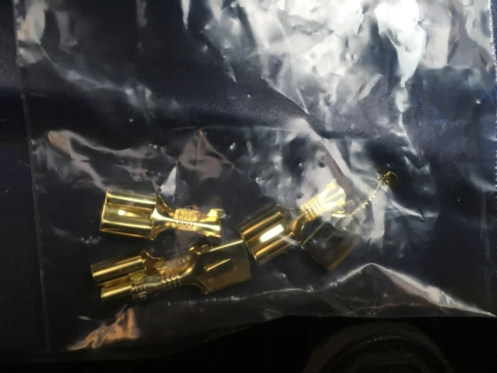
FIG. 2.2 -
Step 3: Run the 10 AWG power cable from the battery to the rear seat
Cut about 10 ft of 10 AWG lead cable for the run from the battery to the back of the car. Feed it through the firewall grommet close to the battery; it emerges under the passenger side, behind the glove compartment and A/C components. Route it through the long green bracket that carries the OEM wiring harness back to the area behind the passenger seat. Inspect the insulation every couple of feet as you pull it through - a hidden chafe here creates a short that is very difficult to find later. Leave slack at both ends so you can re-terminate if a joint goes wrong, then refit the carpet, mat, and plastics.
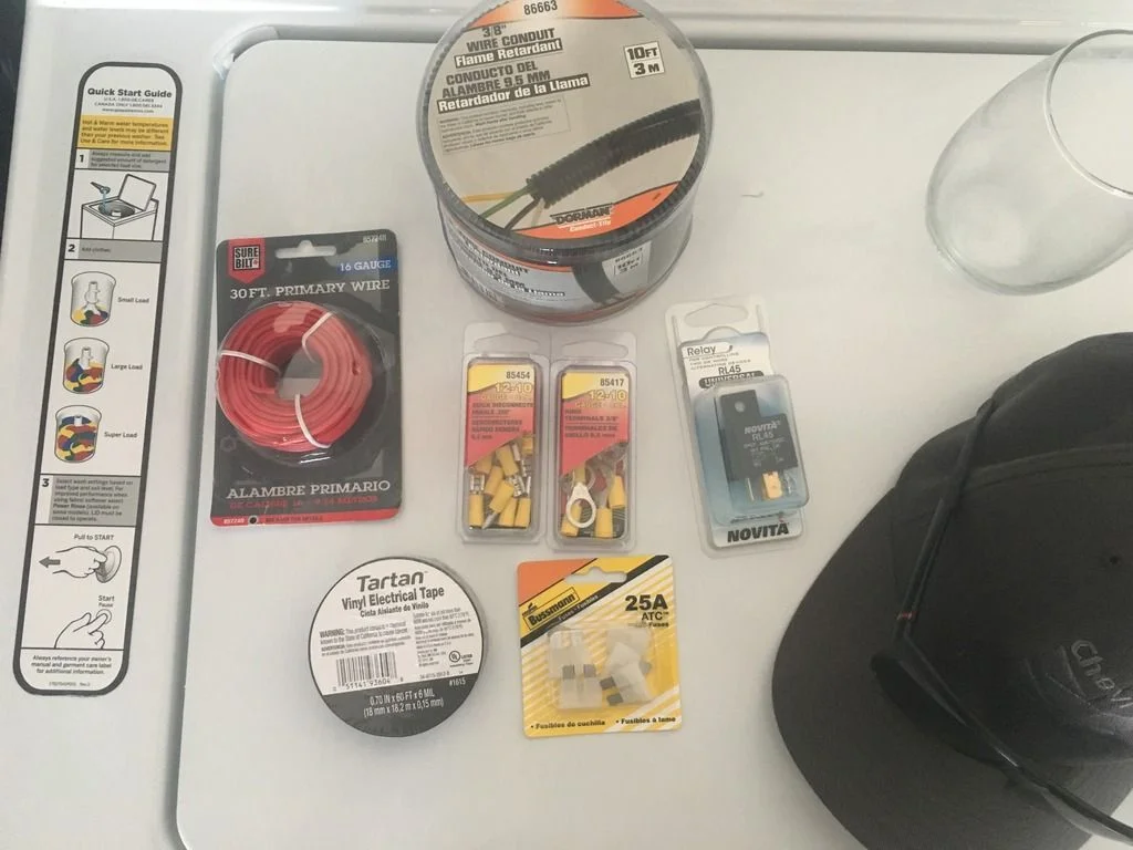
FIG. 2.3 -
Step 4: Terminate the battery feed and connect it to relay pin 30
Strip a short length of insulation from the cabin end of the new battery cable and slide heat shrink well down the wire so soldering heat cannot shrink it prematurely. Crimp on a female spade connector, apply rosin flux, and solder the joint - with the iron at around 750 F the joint should wick solder in about 5 seconds. Do not touch or bend the joint until it has fully cooled; disturbing it creates a cold joint and a poor connection. Once cool, slide the heat shrink up and shrink it. This new battery feed connects to terminal 30 on the relay.
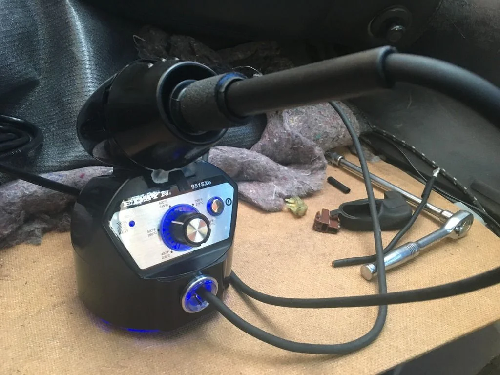
FIG. 2.4 -
Step 5: Connect the original fuel pump power wire to relay pin 85
Find the original fuel pump power wire at the rear of the car (yellow with a green stripe on this 1999 Integra) and cut it, leaving enough length at the plug side to work with and to fit heat shrink. Terminate it with a female spade connector: crimp, solder, and heat shrink. Use a short piece of heat shrink over just the soldered area first, then a longer piece over the whole termination for double protection. This original power wire becomes the relay trigger and connects to terminal 85. If you want a hidden fuel kill switch, extend this trigger wire with 16 or 18 AWG wire, route it through the switch, and then on to pin 85.
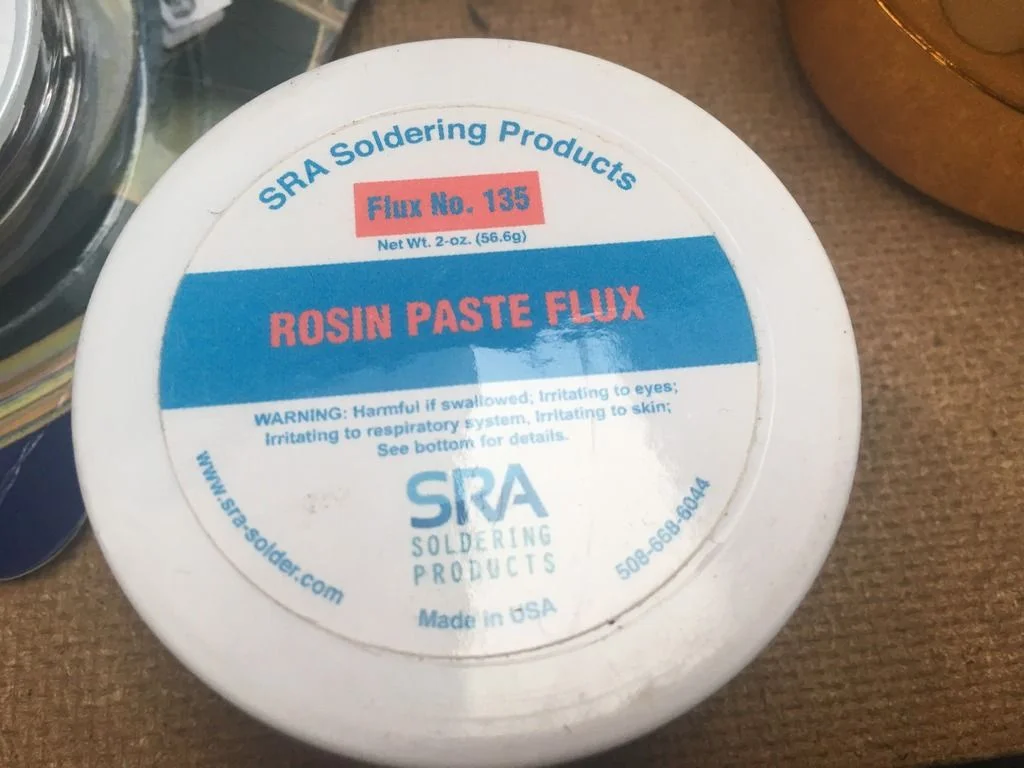
FIG. 2.5 -
Step 6: Connect the original fuel pump ground wire to relay pin 86
Locate the original fuel pump ground wire (black with a white stripe and single silver dots on this car) and repeat the same process: cut it with workable length, strip, crimp a spade connector, solder, and heat shrink. This original ground completes the relay coil circuit and connects to terminal 86. Slide a larger piece of heat shrink over each spade connector, plug it onto the relay, then shrink it so no bare terminal remains exposed.
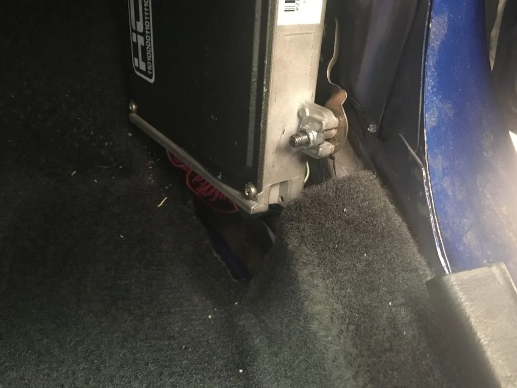
FIG. 2.6 -
Step 7: Run new heavy-gauge power and ground through the fuel pump hanger grommet
Remove the cover over the fuel pump hanger assembly. Run new 10 AWG power cable and 10 AWG ground cable (the same gauge as the battery feed) through the rubber grommet on top of the hanger. These will replace the undersized factory wiring between the plug and the pump.
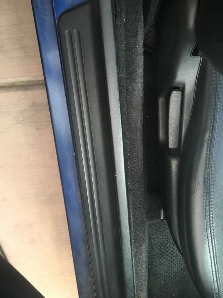
FIG. 2.7 -
Step 8: Fit OEM Honda spade terminals and re-pin the fuel pump plug
Crimp the OEM Honda spade connectors (part no. 07692-0011000) onto the new power and ground cables. Crimping 10 AWG into these terminals is a very tight fit, but they can be crimped, soldered, and heat shrunk successfully. Cut the OEM plug off the fuel pump hanger pigtail, de-pin it, and insert the new terminals - the ground goes in the position nearest the press-in retainer. Make sure each terminal locks in place and cannot be pulled out, then reconnect the plug and refit the hanger cover.
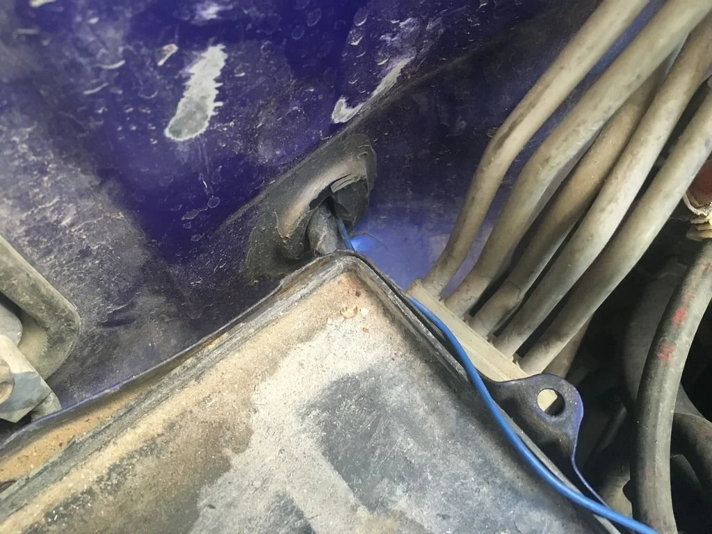
FIG. 2.8 -
Step 9: Connect the new pump power wire to relay pin 87
On the new power wire coming out of the hanger grommet, crimp, solder, and heat shrink a female spade connector. This wire, running from the fuel pump to the relay, connects to terminal 87. At this point the relay wiring is complete: battery feed on 30, original pump power (trigger) on 85, original pump ground on 86, and new pump feed on 87.
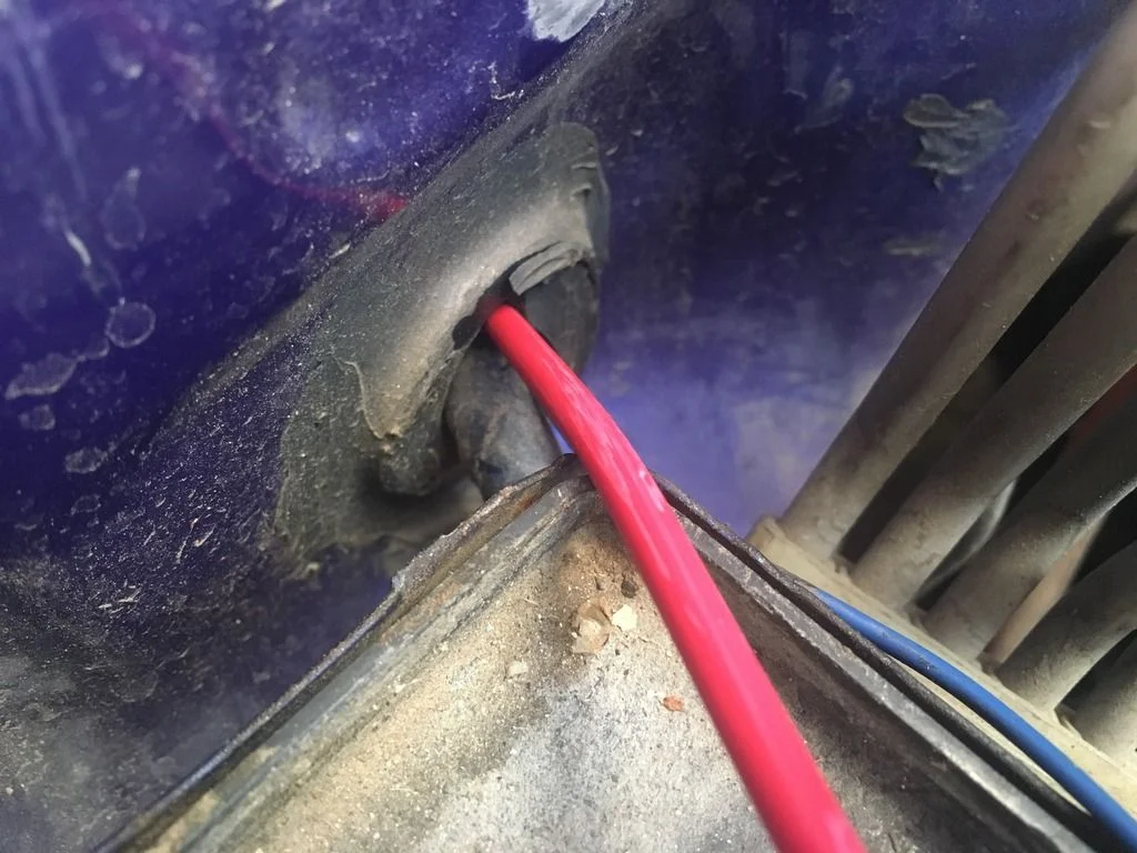
FIG. 2.9 -
Step 10: Ground the new pump ground wire to bare chassis metal
Take the new ground cable exiting the grommet and terminate it with an uninsulated 3/8 in ring terminal - crimped, soldered, and heat shrunk. Run it to the bolt holding the seat belt clip to the chassis. Before bolting it down, clean the contact area to bare metal with coarse sandpaper; a clean, low-resistance ground is essential for a high-current pump.
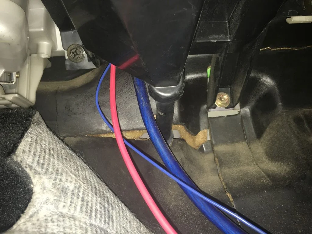
FIG. 2.10 -
Step 11: Install the inline fuse holder at the battery
In the engine bay, splice the 10 AWG inline fuse holder into the new battery feed close to the battery: cut, strip, solder, and heat shrink both joints. Attach a ring terminal on the battery side using the same crimp-solder-heat shrink method, then cover the run with fire-retardant conduit. Fit a correctly sized fuse (25 A ATC used here) only when wiring is complete.
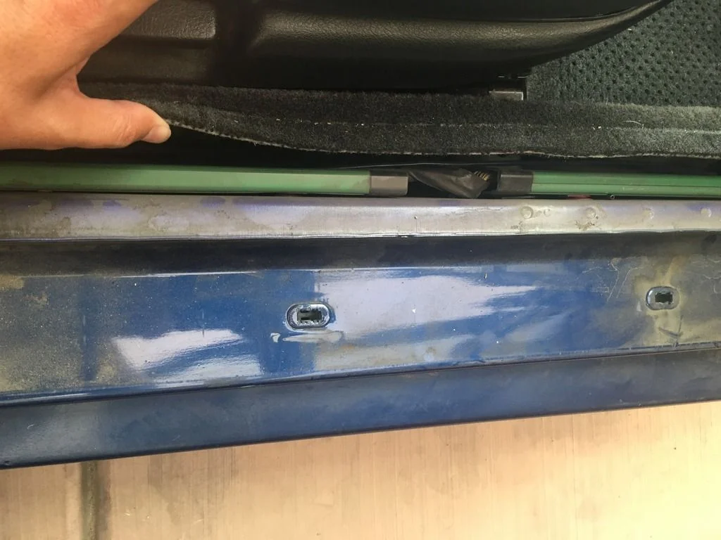
FIG. 2.11 -
Step 12: Test the circuit before installing the pump
Back inside the car, probe the new fuel pump plug with a voltmeter: red probe in the power terminal, black probe on the ground terminal. Confirm the fuse is installed and any kill switch is on, then turn the ignition key to ON without starting the engine. You should read battery voltage at the plug. If you do, the hardwire circuit is complete and ready for the new pump to be wired to the hanger.
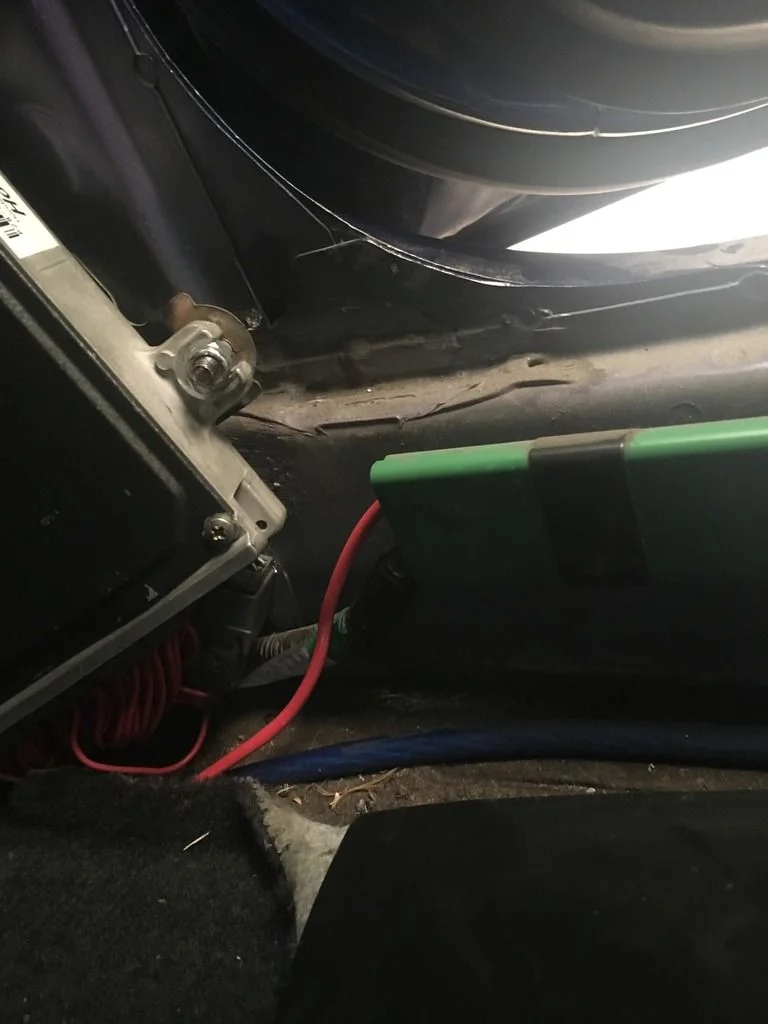
FIG. 2.12
- Use 16 AWG wire only for extending the low-current relay trigger to a kill switch - the 16 AWG shown in the author's photos is not the main power run, which stays 10 AWG throughout (clarified in the replies).
- Double-layer heat shrink every joint: a short piece over just the solder joint, then a longer piece over the whole area for extra protection.
- Slide heat shrink far down the wire before soldering so heat from the iron does not shrink it prematurely.
- Leave extra wire length at both ends of every run so a botched termination can be cut off and redone.
- Buy spare OEM spade connectors (part no. 07692-0011000) - crimping 10 AWG into them is difficult and it is easy to ruin one.
Related procedures
All guides →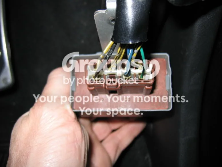
Tap right for next · left for back · Keys: ← → step · Space / PgUp / PgDn scroll · Esc exit