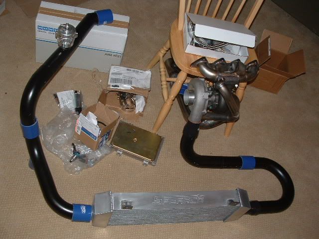
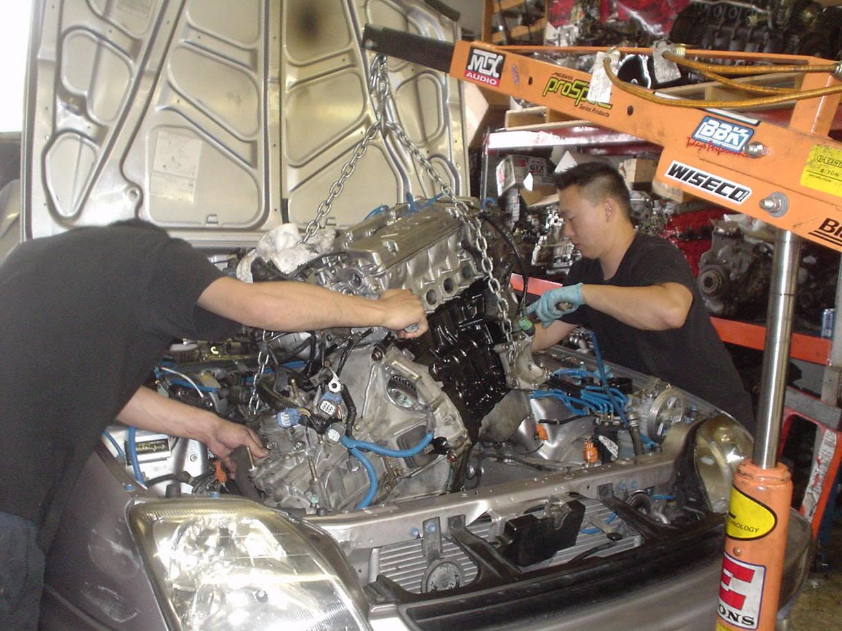
Building a DIY Equal-Length Tubular Turbo Manifold for Honda D-Series
Introduction
This guide covers fabricating an equal-length, tubular 4-into-1 turbo exhaust manifold for a Honda D-series engine from off-the-shelf stainless elbows and a shop-built merge collector, rather than buying a finished unit. The original build was based on a D16Z6 in an EG Civic hatch running a small T25-class turbo, and the same construction method adapts to B-series and H22A swaps with packaging changes (for example, lowering the manifold and clearing the alternator on an H22). A home-fabricated manifold of this style has been used to support well over 200 wheel horsepower, so the payoff is a strong, custom part at a fraction of the cost of a name-brand piece. It is an advanced project: it demands stainless welding skill (or a trusted welder), careful mock-up, and a jig to cut a merge collector accurately. Adapted from a community writeup by Terrabomb on Honda-Tech (https://honda-tech.com/forums/welding-fabrication-53/diy-constructing-sorta-equal-length-tubular-replica-manifold-materials-list-956666/), including corrections from the follow-up discussion.
Reference
Tools Required
- TIG welder (preferred), or MIG welder loaded with stainless wire
- Horizontal or portable metal bandsaw
- Angle grinder with green zirconia-alumina cutting/grinding discs
- Bench vise
- Angle iron and flat steel plate to build a cutting jig
- Clamps
- Tape measure, marker, and layout square
- Deburring tool or file
Parts Required
-
D16Z6 exhaust manifold (head) flange
-
Turbine mounting flange (T25 adapter plate, or a T3 flange)
-
14 x 1.5" ID 304L schedule 40 90-degree elbows, McMaster-Carr #45605K515
-
Length of matching 304L schedule 40 straight tube for extending the outer runners
-
Large-diameter stainless tube stock for the merge collector
-
Stainless filler/MIG wire
-
Steel stock for a manifold brace
Safety Warnings
- ⚠ Stainless welding fumes contain hexavalent chromium; weld only with good ventilation and proper respiratory protection.
- ⚠ Always brace the manifold. An unsupported turbo hanging off the head will fatigue and crack the welds.
- ⚠ Turbine housings and exhaust tubing reach extreme temperatures; heat-shield adjacent components such as the alternator and wiring.
Step-by-Step Instructions
1 Choose the layout and prepare the flanges
Commit to an equal-length, 4-into-1 tubular design, which flows better than a boxed junction. Obtain a head flange machined for the D16Z6 and a turbine flange sized to your turbo, either a T25 adapter plate or a T3 flange. Where engine-bay room is tight, positioning the turbine flange under cylinder one is a common packaging choice. Use thick flange material so the mating faces resist warping as heat cycles through the manifold.
2 Source the tubing and bends
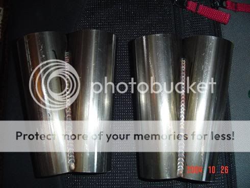
The reference build uses 1.5" ID 304L schedule 40 90-degree elbows, McMaster-Carr part #45605K515, at roughly $5.30 each. Plan on 14 elbows rather than the 12 first estimated, because the two 45-degree pieces coming off the head flange consume an extra bend. Add a short length of the same straight tube to lengthen the outer runners so they clear the inner pair. Be aware of true dimensions: a nominal "1.5 inch" schedule 40 ell actually measures about 1.610" ID with roughly 0.145" wall. Experienced builders favor U-bends over fixed 90s for cutting versatility, and consider 16-gauge (0.065" wall) 321 stainless the ideal turbo-manifold material, with 0.065" being the heaviest wall any race application needs.
3 Shape the runner ends to match the exhaust ports
The head ports are oval while the tube is round. Mark the vertical axis on each runner end and crush it cold in a bench vise until the mouth matches the port outline; schedule 40 tube can be worked to within about 1mm of the flange port shape. As an alternative, 16-gauge 1.75" OD tube comes close to port size straight off the shelf and needs less forming.
4 Mock up and cut the runners for equal length
Trial-fit each runner off the head flange, inserting short straight sections ahead of the bends on the inner cylinders so all four gas paths reach the collector at the same length. Strive for the tightest possible joints, close to air-tight, which limits piece movement while welding and gives cleaner beads. Tack-fit as you go and recheck fitment before committing. Green zirconia-alumina discs remove hard stainless quickly when trimming.
5 Fabricate the merge collector with a jig

Make a 4-into-1 merge collector from large-diameter stainless tube. Build a jig so every cut repeats exactly: weld a piece of angle iron that cradles the pipe at your calculated angle onto a flat steel base, add a clamp to hold the pipe, and run it through the bandsaw. Each of the four pieces receives that same angled cut made twice, rotated 90 degrees from one another; assembled, the four sections taper down into a single outlet. An adjustable jig with several bolt-hole positions in the base lets one fixture produce short, long, or rectangular-mouth collectors.
6 Fit the collector to the turbine flange

A T3 turbine inlet is rectangular, roughly 1.8" x 2.2", while the collector exits nearly square, leaving overlap on the short sides. Resolve it one of three ways: cut the collector mouth to a matching rectangle, add a short transition piece that morphs round into rectangular, or gently form the collector to shape since stainless will bend, especially with heat. Trim any minor overhang so the internal weld sits flush and the flow is not interrupted by a step or wall.
7 Weld the manifold
TIG produces the strongest joints and is the preferred process for a manifold; MIG will work if you switch to stainless wire. The collector interior does not need full welding: fusing the seams without filler and then dressing them smooth adds strength, and sound tacks will hold a water-tight seal. Weld in a logical sequence to control distortion, and back-purge where you can to prevent the inside of the joints from sugaring.
8 Brace, install, and tune
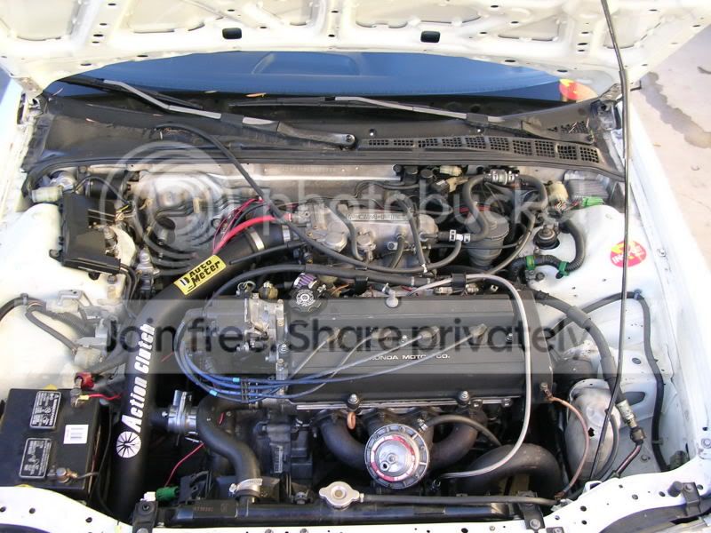
Support the finished manifold with a brace between it and the block or head so the cantilevered turbo weight cannot crack the joints, even with a lighter turbo. Heat-shield nearby items such as the alternator. Once installed, tune conservatively: richen the mixture and raise fuel pressure, run appropriate fuel, and get the car on a dyno before leaning it out. As a reference point, one build using this manifold reached boost onset around 2800 rpm on a T3/TO4E.
Pro Tips
- 💡 U-bends offer more layout versatility than fixed 90-degree elbows when routing equal-length runners.
- 💡 A nominal "1.5 inch" schedule 40 ell really measures about 1.610" ID with roughly 0.145" wall, so order to the true size.
- 💡 Order about 14 elbows rather than 12; the two 45-degree pieces off the head flange use up an extra bend.
- 💡 Green zirconia-alumina discs cut and grind hardened stainless far faster than standard discs.
- 💡 An adjustable jig with multiple bolt-hole positions in the base lets a single fixture cut short, long, and rectangular collectors.
Was this guide helpful?