Two-Stage Dry Nitrous Install and KPro Wiring for a K-Series Honda
Introduction
This guide covers building a two-stage dry nitrous system for a K-series Honda — here a K20A2-swapped EG Civic — and controlling it through a Hondata KPro ECU. Stage one is a single-fogger nozzle in the intake pipe fed by a 10 lb bottle; stage two is a four-cylinder direct-port arrangement fed by a 15 lb bottle. The two stages fire one after the other rather than together, which shortens the time each bottle is under load and limits the pressure drop that makes a single large shot inconsistent late in a run. Both stages are dry, so the extra fuel is added through the port injectors under ECU control instead of through the nitrous lines. The build walks through machining the manifold for the direct port, plumbing the supply, wiring the solenoids and bottle warmers through relays, configuring KPro activation, and — importantly — what dyno testing revealed about jetting, bottle pressure, and why a passive pressure regulator was ultimately removed. It is aimed at experienced tuners: nitrous is unforgiving of wiring mistakes, lean conditions, and inconsistent delivery. Adapted from a community writeup by Moseley on K20A.org (https://www.k20a.org/threads/2-stage-dry-nitrous-setup-installation-wiring-kpro-etc.92898/), including corrections from the follow-up discussion.
Reference
Tools Required
- Drill and bits sized for the direct-port nozzle threads
- Tapered NPT tap for the nozzle bungs (supplied with most direct-port kits)
- Line/tube bender (e.g. NOS) for forming the hard feed lines
- AN and NPT wrenches
- Thread sealant (Permatex or equivalent)
- Compressed air source for clearing machining debris
- Wire crimpers, strippers and a label maker
- Automotive relays, an inline fuse block, and switches
- Multimeter for checking the control wiring
- Laptop with Hondata KManager for KPro configuration
- Access to a chassis dyno and a wideband for tuning
- Spark plugs and a plug-reading loupe for tuning by plug colour
Parts Required
-
10 lb nitrous bottle (stage 1)
-
15 lb nitrous bottle (stage 2)
-
Single-fogger dry nozzle kit for the intake pipe (e.g. Cold Fusion)
-
Four-cylinder direct-port dry kit with nozzles and jets/pills (e.g. Cold Fusion)
-
Nitrous solenoids plus a purge solenoid
-
Nitrous distribution block (equal-flow type preferred)
-
Two pressure-activated bottle warmers
-
Two inline nitrous filters (e.g. NOS)
-
Pressure senders/switches for the bottles and distribution block
-
ID 1000 injectors
-
Marren fuel pulsation damper
-
Assorted jets/pills: .019, .025, .027, .029, and .046
-
Automotive relays and an inline fuse block (e.g. BEP marine)
-
Illuminated dash switches and a steering-wheel-mounted push button
-
-4AN feed line and 3/8 in cushioned clamps
-
Permatex thread sealant
-
NGK spark plugs, heat range 8 and 9
-
Race gas (VP 100, VP Motorsport 109, or C16)
-
Hondata KPro ECU
Safety Warnings
- ⚠ Nitrous is unforgiving: a wiring fault, a lean mixture, or inconsistent delivery can destroy the engine. Treat every stage of the install as safety-critical.
- ⚠ Never power multiple nitrous accessories by tapping thin ignition wiring — it can overload and burn the wire. Feed the solenoids heavy-gauge power directly from the battery through a master relay.
- ⚠ Wire the system so no solenoid can energise unless the ignition is on; drive the master relay from an ignition-switched source and ground it through the master arm switch.
- ⚠ Clear all aluminium swarf from the manifold after drilling and tapping — debris pulled into the runners will damage the engine.
- ⚠ Keep line pressure high enough that nitrous cannot vaporise before the nozzles; low or falling pressure causes erratic flow and dangerous mixture swings. Hotter nitrous needs more pressure to stay liquid.
- ⚠ A passive pressure regulator can clamp flow too far as the bottle empties and lean the shot — watch for it, especially on back-to-back pulls.
- ⚠ Inspect the regulator and every fitting for leaks; on this build the regulator suffered a blown internal o-ring, a leaking output fitting, and a detached gauge face.
- ⚠ If a tuner does not read the spark plugs while tuning nitrous, do not trust the tune — find someone who does.
- ⚠ Size the shot to the traction available; a large hit can spike torque enough to make lower gears unusable and cause wheelspin.
- ⚠ A jagged dyno trace can mean detonation OR inconsistent nitrous flow — confirm air/fuel and knock are safe before assuming it is jetting, and purge the line before adjusting.
- ⚠ Use race or high-octane fuel matched to the shot; an oxygenated fuel will work but you need a lot more of it, and many high-octane leaded fuels are not oxygenated.
- ⚠ Fit blow-down tubes on the bottles to meet dragstrip safety rules.
Step-by-Step Instructions
1 Plan the two-stage series architecture

This build runs two independent dry stages that fire sequentially rather than at the same time. Stage one is a single-fogger nozzle mounted in the intake pipe and fed by a 10 lb bottle; stage two is a direct-port layout, one nozzle per cylinder, fed by a 15 lb bottle. Sequencing the stages keeps each bottle under load for less time, which reduces the mid-run pressure drop that otherwise leans and weakens a single-bottle kit near the top of a pull. Because both stages are dry, all supplemental fuel is delivered by the port injectors under KPro control rather than through the nitrous plumbing. The goal was a safe, repeatable 350 whp on an otherwise bolt-on K20A2, up from 315 whp / 258 tq on the earlier single-fogger setup.
2 Drill and tap the intake runners for the direct-port nozzles

Each of the four runners is drilled and threaded to accept a spray nozzle. Locate the bung as far toward the plenum as hood clearance permits, giving the charge more runner length to mix before it reaches the valves. Use the tapered tap from the kit: because it opens the threads further the deeper it is driven, you can sneak up on the fit by taking successive light passes and test-threading the nozzle between them. The target is a nozzle that snugs up right as it points straight down the runner. Spend the extra time getting that fit correct on all four.
3 Clear all machining debris from the manifold

Drilling and tapping leaves aluminium swarf inside the runners that would be pulled straight into the engine on the first start. Flush the manifold thoroughly with water, then blow compressed air through every runner and passage from several directions until nothing more comes out. Inspect the runners visually before moving on — any fragment left behind is a direct path to engine damage.
4 Bend and fit the feed tubes to the distribution block
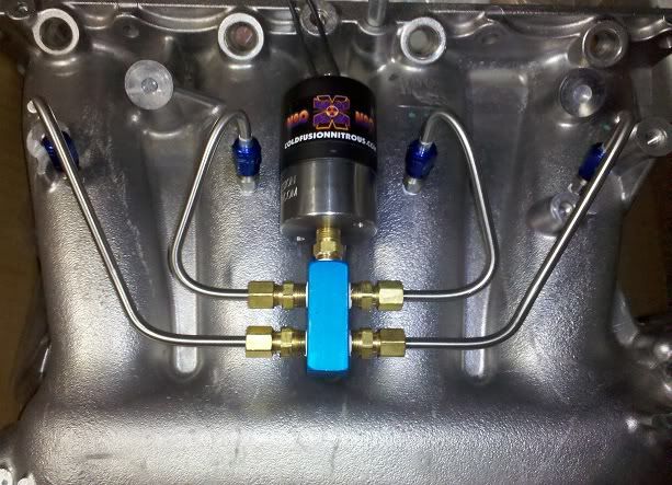
Run a hard line from the distribution block to each nozzle. Use a proper tube bender and form one bend at a time, checking the fit against the manifold after each bend rather than trying to shape a whole tube at once. Be aware that distribution blocks differ: a standard block tends to feed the cylinders unequally, so an equal-flow block is worth fitting even though switching to one means bending a fresh set of tubes.
5 Seal and install the nozzles and fittings
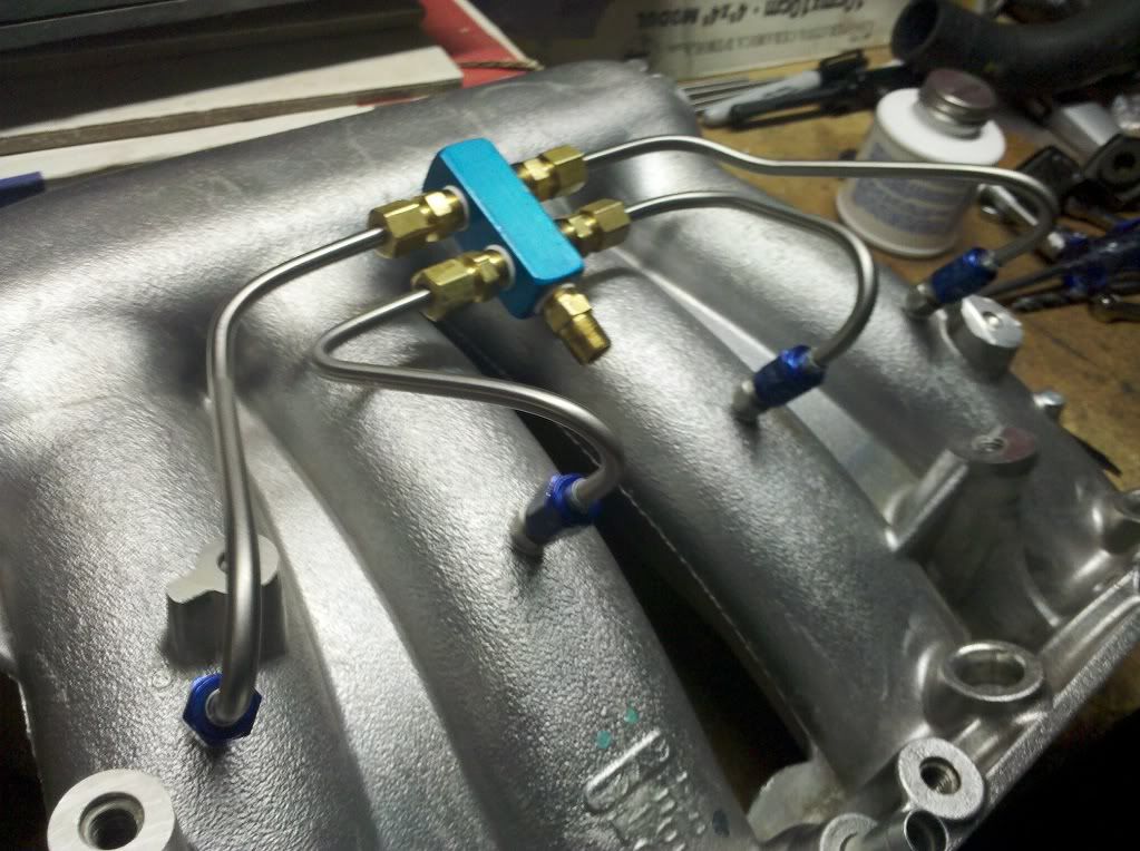
Apply thread sealant to the NPT fittings and the nozzles before final assembly. For fittings this small a thin band around the leading thread is enough — more than that just squeezes out. Thread each nozzle and fitting home, keeping the nozzles aimed down their runners as set during tapping.
6 Plumb the stage-two supply line
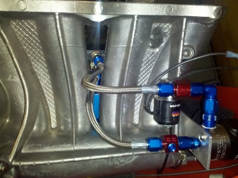
On a direct-port kit the pressure regulator (if used) belongs close to the solenoid, and the solenoid belongs close to the distribution block, so packaging takes some planning. Route the feed line into the regulator, under the manifold, past the purge solenoid, through the main nitrous solenoid, through a port for a pressure sender, then up into the distribution block. Building in that sender port between the solenoid and the block lets you data-log nitrous pressure at the block later. Both stage feed lines land together near the single-fogger solenoid.
7 Wire the solenoid control circuit

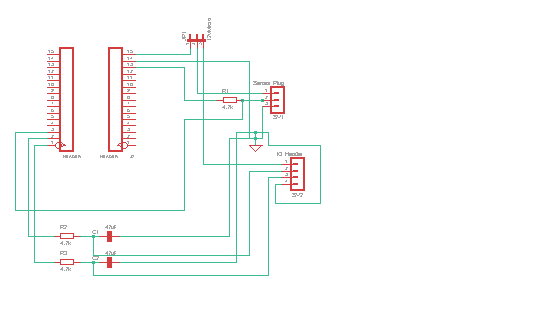
Split the electrics into two circuits — the first serving the solenoids, the arming and stage switches and KPro, the second dedicated to the bottle warmers. No solenoid should be able to energise unless the car is running. Drive a master relay from an ignition-switched source (the black/yellow wire at the under-hood fuse block) and take the solenoids' actual power as heavy-gauge wire straight from the battery/charge harness — never from thin ignition wiring, which can overheat under that load. Ground the solenoids to the chassis. Give each nitrous solenoid its own relay; with the master arm switch on, both sides of those relays are hot, and grounding the coil trips the relay. Route the stage-2 ground to KPro pin E21 and the stage-1 ground through the steering-wheel button to KPro pin E20. The master arm switch grounds KPro pin E29 (which arms the system in KPro), trips the master relay that powers everything else, and grounds the purge button.
8 Wire the bottle-warmer circuit

Keep the warmers on their own circuit that is not tied to the ignition, since they sometimes need to run while the car is off. Control each warmer with its own relay that depends on both a dash switch and a bottle-mounted pressure switch. With the dash switch on, the relay trips and the warmer heats only while bottle pressure is below the switch setpoint (for example 1000 psi); once that pressure is reached the warmer shuts off. Wire an LED into each switch so it lights only while that warmer is actually heating — when the light goes out, that bottle is up to pressure and ready.
9 Configure activation in KPro
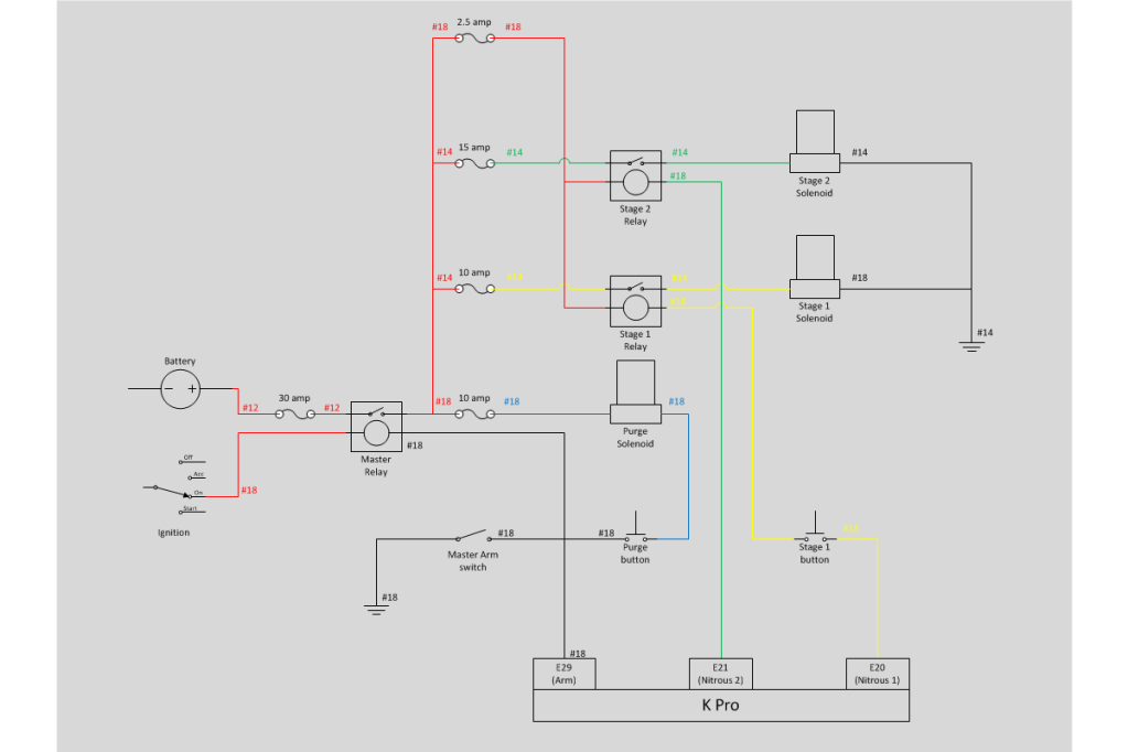
In KManager, map the arm input to pin E29, stage 1 to pin E20 and stage 2 to pin E21. KPro governs when each stage may fire based on throttle position and rpm; for stage 1 both KPro and the steering-wheel button must agree before the solenoid activates. Set up the supplemental fuel delivered through the ID 1000 injectors and the ignition retard for each stage within KPro rather than adding fuel through the dry nitrous plumbing. Note that controlling both stages requires an added pin on the ECU connector.
10 Fit the nitrous filters, senders and line clamps

Install an inline nitrous filter in each feed line in the engine bay to keep debris out of the solenoids and nozzles. Add a pressure sender on each bottle and another on the distribution block; logging both makes a starved shot obvious immediately and shows how a full bottle behaves versus a half-empty one. Secure the -4AN feed lines along the car with 3/8 in cushioned clamps.
11 Tune on the dyno by jet size, pressure and plug reading

Begin conservative and step up jet/pill size while watching torque gain against expectation, air/fuel and knock. As a rough guide, small .019 pills add little, .025s more, and .029s land around 150 hp at 900 psi. If a larger jet fails to add the expected power and the trace turns jagged even though air/fuel and knock look safe, suspect nitrous delivery — a low bottle or a regulator clamping flow — rather than detonation. Purge the line before making an adjustment. Read the spark plugs between pulls to check heat range and whether the cylinders are getting an even charge; drag and V8 communities have good references on reading nitrous plugs. For reference, a .046 pill on the single fogger is a 100 shot.
12 Evaluate, and likely remove, the pressure regulator

The pressure regulator is passive: it caps flow to a fixed amount, but its output pressure tracks its input, so as the bottle empties the input falls, the output falls, and line pressure can drop low enough that nitrous vaporises just before the nozzles — worst during back-to-back hot-lap pulls. Several pressure combinations were tried (around 1200 psi in the bottle with 1050 psi out, and 1050 in with 950 out) and none held consistency once the bottle was part-empty, because too many variables drive the pressure on the input side. The unit itself also failed in three ways: a blown internal o-ring, a leaking output fitting, and a gauge face that detached. Removing the regulator gave more consistent, more explainable results. Final numbers, regulator gone: the single fogger delivered 291 whp on a .046 pill (a 100 shot), while the direct port produced 337 whp on four .029 pills (a 150 shot) — strong given a dyno room above 100°F.
Pro Tips
- 💡 Fire the two stages in series rather than together to minimise how long each bottle stays under load and cut the mid-run pressure drop.
- 💡 Put stage one on a steering-wheel button so you can hold it off until the car hooks at launch, which helps tame wheelspin in the lower gears.
- 💡 Choose an equal-flow distribution block; standard blocks tend to feed the cylinders unevenly.
- 💡 Position the direct-port nozzles as far toward the plenum as hood clearance allows for better mixing.
- 💡 The kit's tapered tap lets you dial in exactly how tight the nozzles seat — take light passes and test-fit between them.
- 💡 A thin band of thread sealant on the first thread is plenty for small NPT fittings.
- 💡 Log nitrous pressure at both the bottle and the distribution block so a regulator set too low or a starved shot shows up early.
- 💡 Work spark-plug reading into your tuning to catch heat-range and per-cylinder distribution issues; good guidance comes from V8 and drag racing sources.
- 💡 Label every wire — a two-stage setup involves dozens of them and a crossed wire is dangerous.
- 💡 Make the switch panel and under-hood harness quick-disconnect (roughly a 30-minute removal) if you run all-motor classes that forbid nitrous hardware.
- 💡 A passive pressure regulator can hurt more than it helps on a dry direct-port kit; be prepared to remove it if consistency suffers as the bottle empties.
Was this guide helpful?