
Turbocharging a Naturally Aspirated Honda: Full Turbo Kit Installation
- Always support the car on two jack stands before working underneath - never rely on the jack alone.
- Disconnect both battery cables before opening the fuel system, and relieve fuel pressure at the fuel filter service bolt before undoing any fuel line. Work with good ventilation; fuel vapor is both toxic and flammable.
- Wear eye protection when cutting metal - cut-off wheel debris flies everywhere.
- Do not run boost on the stock tune: the stock MAP sensor reads only to about 10.63 psi and stock fueling cannot support forced induction. Proper fuel management, bigger injectors and an upgraded pump are essential to avoid engine-destroying lean conditions.
- The turbo oil drain must fall continuously with no kinks or uphill sections, and oil lines near the downpipe must be heat-wrapped, or the turbo will fail.
Introduction
This is a complete walkthrough of converting a naturally aspirated Honda to turbocharging, based on a documented full kit install on an OBD1 Civic/Integra-family engine. It covers removal of the factory intake and exhaust manifold, fitting the turbo manifold, turbocharger and downpipe, plumbing the oil feed and drain, mounting a front-mount intercooler, upgrading the in-tank fuel pump and injectors, adding an injector resistor box for low-impedance injectors, installing a vacuum manifold and boost gauge, and fitting a Hondata-modified ECU. Expect a difficulty of 7-9 out of 10 by import-tuning standards (a full engine build being 10) and allow at least a week of working time so unplanned problems do not leave the car stranded. Adapted from a community writeup by jimmeh on OzHonda (https://ozhonda.com/forum/showthread.php?43515-How-To-Turbocharge-Your-Honda), including corrections from the follow-up discussion.
Procedure
12 steps-
Step 1: Remove the factory intake and exhaust manifold
Locate the intake and header in the engine bay; both are replaced. Remove the intake by loosening the two screw clamps at the throttle-body silicone coupler and the bolt securing the intake to the chassis near the air filter. Jack the car up and support it on two jack stands - much of this job is done underneath. Remove the nine 12mm nuts holding the header to the head studs, then the three bolts joining the catalytic converter to the exhaust. Behind the block, remove the two bolts securing the header support bracket, and the header drops free.
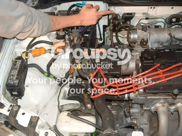
FIG. 2.1 -
Step 2: Assemble and test-fit the manifold, turbo and downpipe
Assemble the manifold, turbo and downpipe on the bench first to verify turbo placement and downpipe routing before installing. Spray PB Blaster on the O2 sensor in the old header so it comes out easily, then thread it into the new downpipe's O2 bung. Slide the turbo manifold onto the exhaust studs. If needed, clock the turbo - rotate the compressor and turbine housings relative to the center housing - by loosening the housing bolts, rotating to suit your plumbing, and retightening.

FIG. 2.2 -
Step 3: Check block clearance and secure the manifold and turbo
Hand-tighten the turbo to the manifold and test-fit the assembly on the engine. It is common on turbo Hondas for the turbo to contact the engine block's web casting; that casting is not structurally critical and can be trimmed back with a Dremel and cut-off wheel until the assembly clears. Once the manifold sits flush against the head and the turbo is clocked correctly, tighten the manifold nuts on the head studs and the turbo-to-manifold bolts fully.
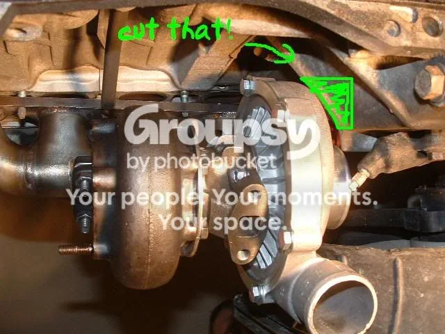
FIG. 2.3 -
Step 4: Remove the oil pan and install the oil drain line
With the turbo mocked up, hold the supplied stainless drain line between the turbo's oil drain hole and the oil pan to find its route. The drain must land in the deep section of the pan, entering at the highest point of that deep section, and the line must run with no sharp turns, kinks or uphill (positive-slope) sections - gravity drainage is critical for turbo seal life. Mark the drain position on the pan with a scribe. Use straight, 45- or 90-degree fittings if needed to avoid kinks, and heat-wrap the line if it passes near the downpipe so the inner rubber does not melt. Then drain the engine oil (17mm drain plug), remove the flywheel cover plate where the transmission meets the block (this hides four of the pan fasteners), and remove all of the roughly 26 bolts/nuts holding the pan. Keep the oil pan gasket for reassembly. Weld in the drain bung, or drill for a weld-less drain fitting, at your mark, then refit the pan and connect the drain line.

FIG. 2.4 -
Step 5: Install the oil feed line
Take the long (approximately 3 ft) thin stainless feed line from the oil line kit. Thread one end into the open port on the oil sandwich/T-fitting installed with the kit, firmly but carefully. Route the other end up to the turbo's oil feed fitting - running it between the intake manifold runners and over the valve cover works well - and tighten it down firmly at the turbo.
-
Step 6: Fit the front-mount intercooler
Fitment varies with the intercooler chosen; compact kits may simply bolt up, while larger cores require cutting the bumper support. Remove the front bumper: five bolts along the top of the radiator support, one bolt inside each fender wheel arch, and about eight screws holding the splash guards. Test-fit the intercooler (supporting it on a jack), mark the required cutout on the bumper support with a marker, and cut with a Dremel cut-off wheel (allow 2-3 hours) or a reciprocating saw - wear eye protection, as metal debris flies everywhere. Mark and drill the intercooler bracket holes in the support, bolt the core in with bolts, nuts and washers, and refit the bumper (five top bolts, both fender screws, approximately six splash-guard fasteners), checking nothing contacts the core.

FIG. 2.6 -
Step 7: Install the upgraded in-tank fuel pump
Disconnect both battery cables first. Fold the rear seat via the key lock on the rear speaker panel, remove the single seat retaining bolt (accessible from inside the trunk), then release the two metal clips at the seat base and lift the seat out to expose the fuel tank access cover. Relieve fuel system pressure: open the fuel cap, then crack loose the service bolt that threads into the banjo bolt atop the fuel filter, holding the banjo bolt with a wrench while loosening the service bolt with a ratchet - keep a rag around the filter for the fuel that escapes. Remove the four access-cover screws, unplug the pump connector, loosen the banjo bolt (again expect a small fuel leak), pull the vacuum hose off its nipple, and remove the six nuts holding the cover plate. Pull the pump assembly up and out at a diagonal. Pop off the green safety clip with a flathead (do not lose it - it is reused), unplug the connector, pull the rubber hose off with pliers, and pull the old pump from its mount past the tight rubber bushing. Compare the new Walbro against the OEM pump before fitting, then reassemble in reverse.
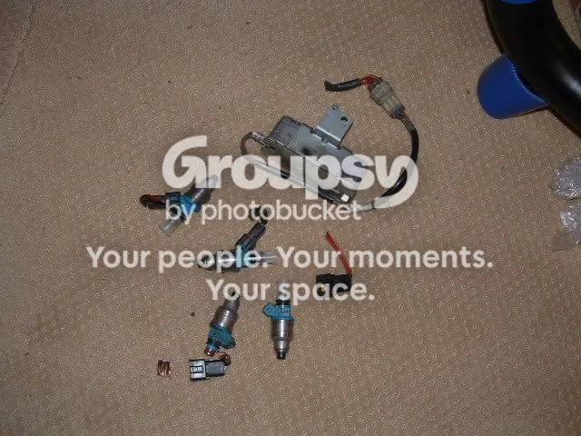
FIG. 2.7 -
Step 8: Install the larger injectors
Fit the larger low-impedance injectors (DSM injectors in this install). Correction from the discussion: on an OBD1 car, DSM injectors clip straight into the stock injector connectors once the small tab in the middle of the injector plug is shaved off with a razor blade - about ten seconds per injector and far better than cutting the harness. (The original method was to splice DSM clips in: each fuel-rail pair has one common yellow/black wire and one unique color, the DSM clips have a common red wire and one unique color - solder common to common and unique to unique; order does not matter.) The DSM injector tips are wider than stock, so either buy larger lower O-rings or carefully bore the hard lower O-rings out to fit (the boring approach ran leak-free in this install). Seat the injectors, refit the fuel rail and tighten its three nuts.
-
Step 9: Wire in the injector resistor box
Low-impedance injectors require a resistor box (junkyard or eBay item; used on some OBD0 Hondas and other cars). On OBD1 Hondas there is a dead-end connector on the harness, found at the engine bay's right corner next to the clutch master cylinder (on OBD2 it is under the intake manifold); it carries the injector power feeds. Pop the protective cover off and, with a multimeter, continuity-test each of the eight wires entering the dead-end connector against the injector clips to identify which four actually feed the injectors - do not copy anyone else's wire positions, as placement can vary; verify on your own car. Cut the four identified wires 2-4 inches from the connector and strip both sides. The resistor box has five wires: solder its single odd-colored wire to all four wires on the dead-end side, and its four common-colored wires to the four injector-side wires. Insulate everything with electrical tape.
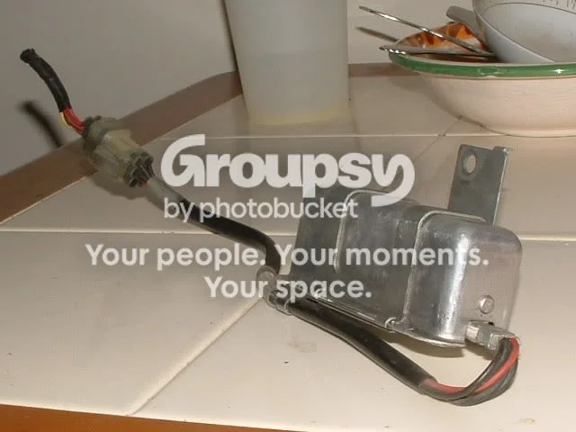
FIG. 2.9 -
Step 10: Mount the vacuum manifold and plumb vacuum sources
Mount the vacuum manifold no more than 5 inches from the main vacuum source (the brake booster line); the center-top of the firewall works well. Using the manifold as a template, drill two mounting holes with a 15/32 in bit and bolt it down (removing the plastic cowl vent in front of the windshield - about ten clips - makes this easier). Sever the brake booster line upstream of (BEFORE) the check valve and splice in a large T-fitting sized for 1/2 in hose, then run 1/2 in vacuum line from the T to the side port of the vacuum manifold. Connect the smaller vacuum lines from the manifold ports to every device needing vacuum, securing all connections with hose clamps or zip ties.
-
Step 11: Install the boost gauge
Wire the gauge's power, ground and dimmer leads at the under-dash fuse box: the 12 V power wire plugs in beneath the radio/cigarette-lighter 15 A fuse for switched 12 V, and the dimming wire beneath the low-beam headlight fuse. Run the boost/vacuum sensing line to a manifold-side vacuum source (a port on the vacuum manifold is ideal - it must be on the manifold side of the throttle so the gauge reads both vacuum and boost), feeding it through the small firewall grommet just right of the battery, then under the dash to the gauge. Mount the gauge in view - on the steering column, for example.
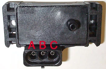
FIG. 2.11 -
Step 12: Fit the tuned ECU and upgraded MAP sensor
The easiest part and the last. On the passenger side, pull back the carpet under the dash (a few clips) to expose the ECU against the side wall. Remove the 10mm nuts/bolts holding it, unclip the harness connectors, and swap in the Hondata-equipped (or otherwise chipped/standalone) ECU. If you are running more than about 10.63 psi, the stock MAP sensor cannot read your boost - fit the 2-bar or 3-bar MAP sensor and have the tune calibrated for it. Also fit the copper spark plugs two heat ranges colder than stock. Refill all fluids, double-check every oil, fuel, vacuum and charge-pipe connection, and have the car properly tuned before applying boost.
- Correction from the discussion: DSM injectors clip into the stock OBD1 injector plugs once the center tab on the injector is removed with a razor blade - avoid chopping the injector wiring.
- Correction from the discussion: make sure the turbo oil drain line points downward into the pan along its whole run; a drain that climbs toward the pan will cause drainage problems and smoke the turbo seals.
- Choose an intercooler that maintains frontal area without excessive height and you may avoid cutting the bumper support at all.
- Ratcheting wrenches and a large variety of sockets pay for themselves in the tight spaces around the turbo and downpipe.
- Buy a quality boost gauge - cheap eBay gauges are notoriously inaccurate.
- A vacuum manifold is not strictly required but keeps vacuum lines organized and provides reliable ports for the wastegate, blow-off valve and gauges.
Related procedures
All guides →

Tap right for next · left for back · Keys: ← → step · Space / PgUp / PgDn scroll · Esc exit