Blueprinting a Honda Four-Cylinder Bottom End: Precision Measurement for a Race Build
Introduction
This guide covers precision blueprinting of a Honda four-cylinder bottom end, the measurement-driven approach used for a serious street or race build rather than a basic rebuild that relies only on plastigauge, a torque wrench, and feeler gauges. The methods apply to the B, D, F, and H series (and, by extension, the K series, whose bearing thicknesses are believed to match), and cover the same fundamentals whether the block sits in a Civic, Integra, Prelude, or Accord. The goal is to independently verify every clearance and geometry figure that a machine shop or a previous builder handed you, because a single wrong clearance, a taper you never measured, or a fastener that was not properly secured can destroy a fresh motor. You will measure pistons, bores, crank journals, and main bores; select bearings from the Honda color chart; check crank straightness and main-bore alignment; correct every figure for thermal expansion; and confirm the result before it runs. Treat the machine shop's work as something to be checked, not trusted on faith. Adapted from a community writeup by 98vtec on Honda-Tech (https://honda-tech.com/forums/engine-machining-assembly-164/diy-engine-block-blueprinting-techniques-3138527/), including corrections from the follow-up discussion.
Reference
Tools Required
- Outside micrometers covering 1-2", 2-3", and 3-4" ranges, resolving to 0.0001" or finer
- 0-1" micrometer with rounded anvils reading to 0.00005" for bearing shell thickness
- Micrometer setting standards / calibration gauges
- Micrometer stand (to keep hand heat off the tool during readings)
- Digital bore gauge resolving to 0.0001"
- Vernier caliper
- Depth gauge
- Feeler gauge set
- Dial indicators with a magnetic base and V-blocks
- Long precision straightedge
- 1/2" torque wrench (25-250 ft-lb) and 3/8" torque wrench (0-75 ft-lb)
- Plastigauge
Parts Required
-
Main and rod bearing shells, color/thickness-graded to the target oil clearance (per the Honda bearing color/thickness chart)
-
Plastigauge
-
Thread-locking compound
-
OEM Honda crankshaft (preferred over budget aftermarket cranks)
-
Machine-shop bore, hone, and align-hone service as required by your measurements
Safety Warnings
- ⚠ Out-of-round bores lead to poor ring seal, which in turn causes oil consumption, low vacuum, detonation, and accelerated ring, cylinder, and piston-skirt wear; do not sign off on a marginal bore.
- ⚠ DIY straightedge-and-feeler checks resolve only to about 0.001"; do not treat them as a final verdict on main-bore alignment or crank straightness for a race engine, confirm on shop equipment.
- ⚠ Do not take a machine shop's or prior builder's figures on faith; wrong clearances and wrong parts in a fresh motor can destroy it within a handful of passes.
- ⚠ Every fastener bolted to the crank must be torqued to spec and secured, torque-to-spec alone did not prevent a documented failure where the flywheel bolts, balancer, and crank bolt all backed out.
Step-by-Step Instructions
1 Assemble a precision measurement kit
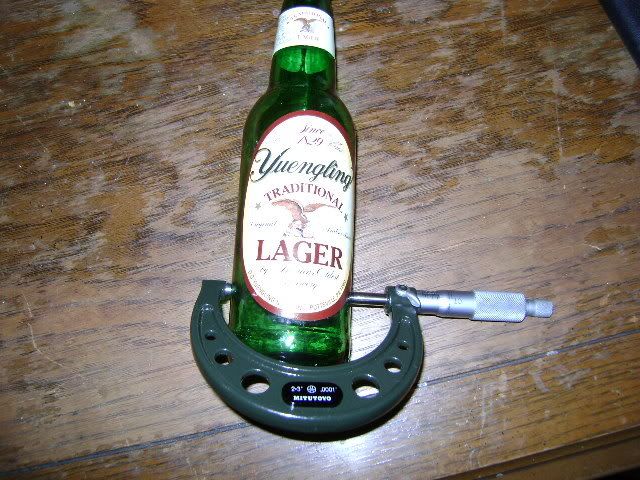
Gather instruments with enough resolution to matter. Bore gauges and micrometers should read to at least 0.0001"; a dedicated 0-1" micrometer with rounded anvils that resolves to 0.00005" is used for measuring bearing shell thickness. Include a micrometer stand: holding a mic in your hand warms it and slowly shifts the reading, so a stand keeps successive measurements consistent. Round out the kit with a bore gauge and its extensions, a caliper, a depth gauge, a feeler set, dial indicators on a magnetic base, and torque wrenches sized for both light and heavy fasteners.
2 Calibrate and read the micrometer correctly
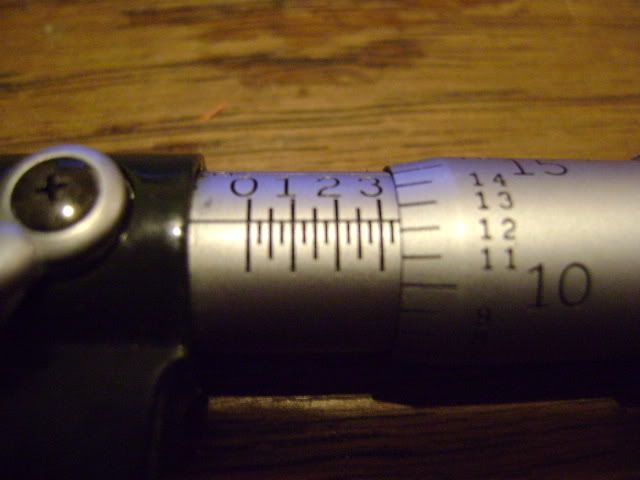
Before measuring anything, zero the mic against its setting standard so you know it reads a true zero; buy the standards separately if they did not come with the tool. Work quickly on each reading, because heat transferred from your hand grows with contact time and corrupts the result. When the part is round, center the anvil and spindle on it so the gap is even all the way around both faces. Close the mic until it slides off snug, with no force and no slop, then lock and remove it. Read the sleeve first (each mark is a quarter division), add the thimble figure, then read the vernier line that best aligns for the final digit.
3 Measure and log each piston
Measure every piston across its thrust faces at roughly the midpoint of the skirt, where the bulk of thrust wear concentrates and where you want clearance set. Record each figure against its cylinder number so the bore work later can be matched piston by piston.
4 Map bore taper and out-of-round
Dial the bore gauge to a fixed reference size using a micrometer, then zero the gauge against it. Set the gauge in each cylinder on one axis and read near the top, the middle, and near the bottom, rocking it slightly to capture the smallest value at each height. The spread between those three points is the bore taper. Repeat 90 degrees around on the other axis at the same heights; the difference between the two axes at a given height is the out-of-round. Out-of-round matters more than taper for ring seal, so weight it accordingly.
5 Set piston-to-wall clearance and specify machining
Subtract the piston diameter from the bore to get piston-to-wall clearance, and choose your target for the engine's actual duty: a high-boost, lower-RPM turbo motor and a naturally aspirated screamer want very different figures because heat and RPM both drive expansion. Remember that a forged piston expands more than a cast one and needs more room. In almost every case the block then goes to a machine shop to bore and hone to the clearance you specified; state the crosshatch angle and surface finish you want, since a poor hone, not the rings, is the usual cause of blow-by.
6 Measure crank journals and select bearings
Mic each main and rod journal on the vertical axis, 180 degrees from the bearing parting line, which is where the shell is thickest and where the standard measurement is taken. Measure the corresponding crank bores. The bore-minus-journal figure, less the shell thickness, gives oil clearance; pick the bearing grade from the Honda color/thickness chart, whose thicknesses are shared across the B, D, F, and H series (note that the H and F series have no RED grade). Also check journal roundness: a journal 0.0005" out of round quietly shrinks a 0.0020" clearance toward 0.0015", which matters at high RPM.
7 Check crank straightness and main-bore alignment
Support the crank in V-blocks and sweep a dial indicator along it to read straightness and runout. Lay a long precision straightedge across the main saddles to check bore-line alignment, and use the same edge to check deck and head flatness. A straightedge-and-feeler check is a DIY sanity test only, resolving to about 0.001"; an align-honed block or a single main sitting 0.0005" off centerline changes running clearances and should be confirmed on shop equipment.
8 Correct every clearance for thermal expansion
Parts are fitted at room temperature, generally defined as 20 to 25 degrees C (68 to 77 F), but the engine runs far hotter, and a cold garage in winter is not room temperature. Iron and steel grow by about 0.000006" for each inch of length with every degree F of rise, while aluminum moves nearly double that at roughly 0.000012". A steel pin in an aluminum piston set to 0.0005" cold opens to at least 0.0019" at 250 F. Factor operating temperature into each clearance. Rod stretch matters too: an aluminum rod can grow as much as 0.030" at peak RPM, so build that into piston-to-valve and piston-to-head figures.
9 Verify the final assembly with plastigauge
With the rotating assembly torqued together, run plastigauge on the bearing clearances as a final cross-check. It catches a defective shell or a measurement you botched without you having to trust a single reading. Builders fully confident in their tools and technique may treat this as optional, but it is cheap insurance on an expensive motor.
10 Unitize and secure the rotating assembly
Every component bolted to the crankshaft, the clutch pressure plate, flywheel, and front pulley or balancer, must be torqued to specification and thread-locked so nothing can back off. If one end loosens, the rest of the assembly follows, and secondary damage such as a shattered oil pump usually follows with it. For valvetrain planning context, an Integra Type R runs about 42 lb of seat pressure new and 37-39 lb once run in, a useful reference point when deciding spring pressure for a high-lift, high-RPM cam.
Pro Tips
- 💡 Honda inline-four cranks are inherently well balanced because the counterweights oppose each other, so aftermarket balancing is usually unnecessary; from that standpoint an OEM crank is hard to beat.
- 💡 Even builders who trust their micrometers often plastigauge from time to time when something does not look right.
- 💡 Build a working relationship with a machinist fluent in Honda four-cylinders; getting a proper hone on these blocks is genuinely difficult because there is so little room beyond the main webs to run the tool deep enough for correct dwell at the base of the cylinder.
- 💡 Measure at a controlled, stable room temperature; specs assume it, and a freezing garage will skew your numbers.
Was this guide helpful?