K-Series Swap Charge Harness Wiring (Civic EG/EK, Integra DC)
Introduction
A K-series engine swap into a Honda Civic (EG or EK) or Acura Integra (DC2) requires rebuilding the charging and starting circuit, because the donor K20 distributes power differently than the D- or B-series it replaces. This guide explains how to adapt an RSX Type S (or EP3 Civic) charge harness so it feeds the starter, alternator, and under-hood fuse box correctly in the swapped chassis. It covers separating the low-current engine sensor leads that ship bundled inside the charge harness, choosing between the factory three-cable layout and the simplified single-feed (ChaseBays-style) approach, sizing and terminating the heavy battery cables, fabricating the fuse-box jumper, grounding the system, and testing the result so the starter cranks and the alternator charges. Read it before cutting anything: several builders found that with the battery and fuse box left in their stock locations, the harness can be adapted with almost no cutting at all. Adapted from a community writeup by k20jonny on K20A.org (https://www.k20a.org/threads/faq-how-to-wire-charge-harness-eg-dc-ek.91212/), including corrections from the follow-up discussion.
Reference
Tools Required
- Heavy-cable lug crimper (e.g., Hobart 770122 Lug Crimper)
- Soldering iron or small torch and electrical solder
- Bench vise
- Heat gun for heat-shrink tubing
- Wire cutters and strippers rated for 2-4 gauge cable
- Drill and bits (approx. 1/4 inch)
- Dremel or rotary tool to cut and shape the jumper plate
- Multimeter for continuity and charging-voltage checks
- Sockets and wrenches for battery, fuse box, and ground fasteners
Parts Required
-
K-series (RSX Type S / EP3) charge harness, donor
-
4 gauge cable for the battery, starter, fuse box, and alternator runs
-
2 gauge cable for the battery-negative-to-chassis ground
-
8-10 gauge cable for additional engine and transmission grounds
-
4-gauge ring terminals, 1/4-inch hole (e.g., Stinger 4 Gauge Ring Terminals)
-
Starter lug, 3/8-inch stud (e.g., Monster 200 Crimpable Ring Terminals, 4-gauge)
-
Solid flat copper or brass bar stock for the fuse-box jumper (e.g., K&S)
-
Battery terminals and red positive terminal cover
-
Heat-shrink tubing and wire loom
-
Inline fuse or resettable circuit breaker (optional)
Safety Warnings
- ⚠ Keep the alternator cable away from the accessory belt and any sharp or hot surfaces; a rubbed-through cable is the most common cause of a fuse blowing the moment the key is turned.
- ⚠ The starter feed carries very high current; use properly sized cable and terminals and torque the connections, or the joint can overheat.
- ⚠ Disconnect the battery before terminating or bolting up any of the heavy power cables to avoid a dead short.
Step-by-Step Instructions
1 Separate the sensor leads from the power cables
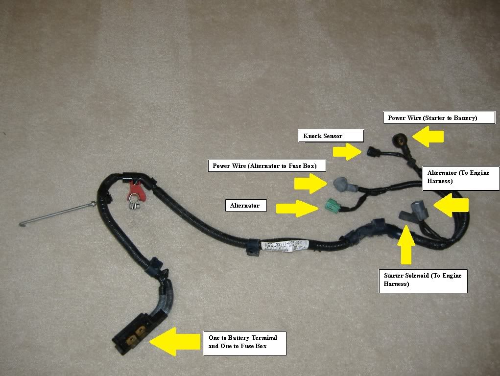
The bundle sold as a K-series charge harness is not purely heavy-gauge wiring. Mixed into it are low-current signal leads for the knock sensor, the alternator, and the starter solenoid, which actually belong to the engine harness. Take the harness apart and identify each lead. Solder, heat-shrink, and loom the knock-sensor, alternator, and starter-solenoid signal wires into the engine harness where they naturally route. This removes the excess slack and leaves you with only the three heavy power cables to manage as the true charging circuit. Doing this once is far cleaner than trying to route the thin signal wire alongside the thick battery cable.
2 Choose the charging circuit layout

Two proven topologies exist. The factory-style layout uses three heavy cables: battery positive to the starter, battery to the under-hood fuse box, and fuse box to the alternator. The simplified single-feed layout (how ChaseBays and Rywire build theirs) runs one main cable from the alternator to the starter and bridges the two fuse-box terminals with a jumper, eliminating a separate distribution run; this is handy when the battery is relocated to the trunk. Keep the current path correct: run the starter cable to the battery and on to the fuse box, with the alternator tied to the fuse box. One builder pointed out that the original poster's early photos had the starter and alternator cables reversed. Settle on battery and fuse-box locations now, since a trunk-mounted battery changes both cable length and gauge.
3 Size and cut fresh battery cables
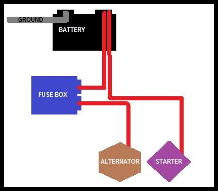
Do not splice or extend the factory heavy cables; lengthening 4-gauge cable by crimping or soldering is discouraged, so cut new cables to the exact runs your chosen layout needs. Most builders used 4 gauge for all three power runs (battery to starter, battery to fuse box, fuse box to alternator) and 2 gauge for the main battery-negative-to-chassis ground. The original poster believed the factory cable is 4 gauge, while another builder cited 6 gauge as the Honda-specified size; either is acceptable, and going one size larger rarely hurts except on long relocated runs where voltage drop matters. On the single-feed layout, the short alternator-to-starter link is commonly run in 8 or 10 gauge.
4 Terminate the cables
Crimp ring terminals matched to each stud. The fuse box and alternator take 4-gauge ring terminals with a 1/4-inch hole (for example, Stinger 4 Gauge Ring Terminals, 1/4"). The starter stud is larger, so fit a 3/8-inch-stud lug there (for example, the Monster 200 crimpable lug in 4-gauge, sized for a 3/8-inch stud). A proper heavy-cable crimper such as the Hobart 770122 Lug Crimper produces a solid crimp. For 8-gauge grounds, where solder slugs are not practical, clamp the lug upright in a vise like a cup, heat it until solder flows and fills it past half, then push the wire in while it is still molten and hold until it sets; crimping first and then soldering works too. Seal every joint with heat-shrink tubing.
5 Fabricate the fuse-box jumper

When a single cable feeds the fuse box, its two terminals must be bridged so both ports carry 12 volts and the alternator feed can cross over to the starter side. Instead of a bulky jumper wire, cut a U-shaped piece of solid flat copper or brass bar stock (steel or aluminum also work) and drill two holes to match the fuse-box screw spacing, roughly 1/4 inch or just large enough for the screws. Stack it screw, cable lug, jumper plate, fuse box, with the plate seated against the fuse box, and scuff all mating faces for a clean electrical contact. Solid bar stock such as K&S from a hobby or hardware store is thicker and more reliable than the thin plates cut off the OEM fuse-box lugs. Note that builders debated whether the jumper is even required, since the two ports can read continuous on a meter; treat it as necessary for the single-feed layout unless you have confirmed your fuse box actually carries current across both ports under load.
6 Establish the grounds
Run the main 2-gauge ground from the battery negative terminal to the chassis. The starter draws its cranking current through its mounting, so the transmission housing where the starter bolts in must be solidly grounded; carry a ground from the battery to both the frame and the transmission case. One builder used two grounds rather than the commonly suggested three, without any trouble: a 10-gauge lead tying the timing cover to the strut mount, plus an 8-gauge lead from a transmission bolt near the starter across to the chassis. Weak grounds are a frequent cause of poor cranking, so do not skimp here.
7 Route and secure the cables
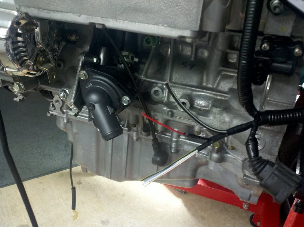
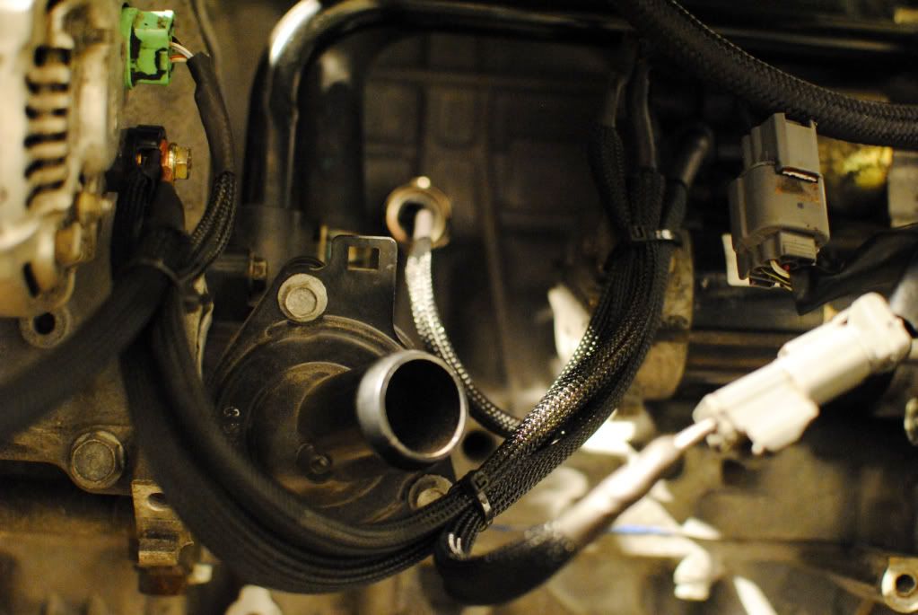
Run the alternator cable down the timing-chain side of the engine, keeping it well clear of the accessory belt, and leave enough slack for the engine to rock on its mounts so nothing is pulled tight and snapped. Support the harness with brackets so the heavy cables do not hang on their terminals; the throttle-cable and idler bracket bolt hole on the block and a second anchor on the strut tower are convenient mounting points.
8 Add an inline fuse or breaker (optional)
For protection on the main feed, fit an inline fuse or a resettable circuit breaker between the battery and the fuse box, as the ChaseBays reference diagram shows. This is especially worthwhile on a trunk-mounted battery with a long cable run, where a chafed cable could otherwise dump the full battery into a short.
9 Test the charging system and troubleshoot
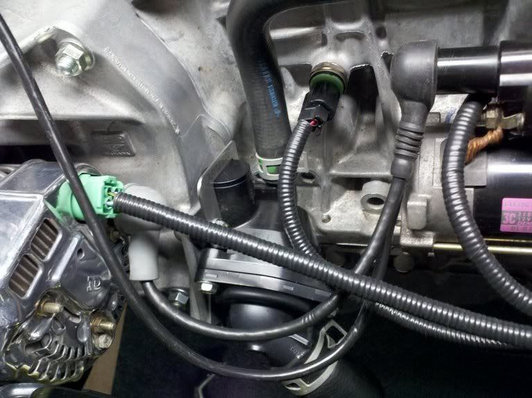
With everything connected, check continuity, then start the engine and read charging voltage; a healthy system sits around 14 to 14.5 volts. If the alternator fuse (Fuse 15 in an EK9) blows the instant the ignition is switched on, suspect a chafed cable grounding against bare metal and inspect the entire harness, including any leads routed behind the steering rack. If voltage jumps around in datalogs even though the cables read 14 to 14.5 volts, test the battery: a weak internal cell can produce exactly this behavior.
Pro Tips
- 💡 If the battery and fuse box stay in their OEM locations, a fully disassembled RSX Type S charge harness can often be adapted with no cutting; only the fuse-box connector ends need modifying.
- 💡 Prefer making new, correctly sized cables over splicing the factory heavy wire; heavy-gauge splices are discouraged and add failure points.
- 💡 On a relocated (trunk) battery, size up the cable to offset voltage drop over the longer run.
- 💡 Scuff every clamped contact surface (fuse box, jumper plate, and lug) so the connection is metal-to-metal.
- 💡 Leave slack in the engine-bay cables so normal engine movement does not tug on the terminals.
Was this guide helpful?
