Honda Fit (GD): Build a JDM-Style LED Third Brake Light
Introduction
This guide covers building a custom LED replacement for the center high-mount (third) brake light on the first-generation Honda Fit / Jazz (GD), reusing the factory housing and red lens. Instead of paying around ninety dollars for the JDM LED unit, you populate the original lamp with a small array of LEDs mounted on perfboard for the same look at a fraction of the cost. The stock incandescent bulb is removed and replaced by six 5mm LEDs wired through a current-limiting resistor so they survive the car's charging voltage. It applies to the GD-chassis Fit/Jazz hatch, and the same approach transfers to any lamp housing with a similar bulb socket. Expect basic soldering and a bit of trial fitting. Adapted from a community writeup by koolkevin1107 on FitFreak (https://www.fitfreak.net/forums/fit-interior-exterior-illumination/8530-jdm-style-3rd-brake-light-diy.html), including corrections from the follow-up discussion.
Reference
Tools Required
- Flat-head screwdriver
- 10mm socket or wrench
- Scissors or a rotary tool for cutting perfboard
- Soldering iron and solder
- Hot glue gun
- 9 volt battery for bench testing
- Wire strippers/cutters
Parts Required
-
Six 5mm LEDs, orange-red, roughly 8000mcd or brighter (Superflux 4-chip LEDs are a flatter, wider-beam alternative)
-
Perforated prototyping board (RadioShack LED perfboard works; roughly half a board is needed)
-
Current-limiting resistor(s) sized to your LEDs (commonly 180-240ohm)
-
Thin hookup or speaker wire
-
Hot glue sticks
-
Solder
Safety Warnings
- ⚠ A current-limiting resistor is mandatory. LEDs run with no resistor on the car's roughly 13.8 volt charging system will look bright at first and then burn out within about a week.
- ⚠ The third brake light is a regulated safety lamp. Keep it red, steady (non-flashing), and in its factory location; word or pattern inserts may be illegal in your area.
- ⚠ Always confirm the light activates with the brake pedal before driving.
Step-by-Step Instructions
1 Remove the third brake light from the hatch
Raise the hatch and work from the inside. Pop the trim cover away from the lamp with a flat-head screwdriver, then back out the two 10mm bolts securing the assembly to the hatch. Unplug the bulb harness connector and lift the whole unit free. Move to a bench for the rest of the work.
2 Open the housing and remove the lens and bulb hardware
The red lens is retained by four clips around its edge. Gently release each clip with a flat-head screwdriver and lift the lens off. Behind it, press the metal retaining bracket inward at its clip points to free it as well, then pull the original bulb from the socket. You are left with the bare plastic housing and its wiring socket.
3 Choose LEDs and plan the layout
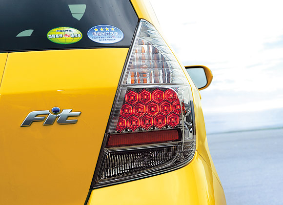
Six 5mm LEDs reproduce the factory JDM appearance, though you can run more or arrange them in any pattern. Favor orange-red LEDs over deep red: OEM rear lighting sits near 625nm, orange-red matches that DOT shade, and it transmits better through the existing red lens than a deeper 638nm red. Bare LEDs read closest to the OEM tint; a red lens over them is fine as long as the emitter is in the red range. Around 8000mcd is a reasonable brightness target.
4 Cut the perfboard to fit the lens
Lay the red lens on a piece of perforated prototyping board and trace its outline. Cut just outside the line, then dry-fit the board into the housing and keep trimming until it seats below the level of the lens clips; if it sits too high, the lens will not clip back down. The board is brittle, so cut in small passes and avoid flexing it.
5 Mount and align the LEDs on the board
Mark the center of the board and space the LEDs evenly across it; roughly eight holes apart spreads six across the width cleanly. Push each LED through from the front. Keep polarity consistent, for example bending every positive leg one way and every negative leg the opposite way so you can tell them apart later. For the two outermost LEDs, fold their legs flat toward the center so they clear the back wall of the housing. Anchor each LED with a dab of hot glue on its legs and let it set.
6 Size the current-limiting circuit
Do not run the LEDs directly off the brake feed with no resistor. Wire them so a current-limiting resistor sets the current for a series string. Measured forward voltage is roughly 2.3v per LED and the feed sits around 12.25v, so a resistor across a series of five LEDs targets about 20mA: [{12.25v-(2.3v*5)}/.02A] = 19.23mA. In practice values in the 180-240ohm range are common (banks of a few LEDs each fed through a 240ohm resistor works well). Plug your exact LED forward voltage and count into an online LED resistor calculator to confirm the value.
7 Solder the wiring
Solder the resistor in line with the positive side of its LED string, then join the LED legs into a common positive bus and a common negative bus using short lengths of thin hookup or speaker wire; current draw is low, so light gauge wire is fine. Bring every string together into a single positive and single negative lead. Keep the joints tidy and insulated where leads could touch.
8 Bench test with a 9 volt battery
Before closing anything up, touch the two leads to a 9 volt battery to confirm all LEDs light. Remember LEDs conduct in one direction only, so if nothing lights, swap the leads. Fix any dim or dead LED now while the board is still accessible.
9 Reassemble the lamp unit

Refit the metal bracket onto the plastic housing the way it came off, then feed the two output leads out through the existing wiring-socket hole. The bracket adds thickness top and bottom, so the board tends to hold snug on its own. Seat the leads into the corners of the bulb socket connector. The LEDs stand about 0.5mm too tall for the lens to clip effortlessly, so either rest the lens on the LEDs and tape or glue it in place, or carefully force it back into its four clips for a flush OEM look. Retest after forcing the lens in case a joint shifted.
10 Reinstall on the car and verify operation
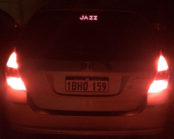
Mount the assembly back onto the hatch with the two 10mm bolts and reconnect the harness plug. Before you finish, have someone press the brake pedal and confirm the light comes on. If it stays dark, the polarity is reversed at the socket, so swap the two leads and test again. Once it lights with the pedal, refit the interior cover.
Pro Tips
- 💡 Orange-red LEDs near 625nm match OEM/DOT red and pass through the red lens better than deep red.
- 💡 Use an LED resistor calculator (for example metku.net or led.linear1.org/led.wiz) to size resistors for your specific LED forward voltage and count.
- 💡 Superflux 4-chip LEDs sit flatter and throw a wider, more even beam, which makes them easier to pack into the housing and brighter off-axis.
- 💡 Fold the legs of the outermost LEDs flat toward the center so they clear the rear wall of the housing.
- 💡 Prebuilt diffused LED light bars were reported as disappointingly dim, so a purpose-built LED board generally gives a better result.
Was this guide helpful?