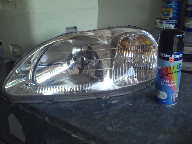
Honda Civic EK Daytime Running Light Conversion (Relay-Driven Low Beams)
Introduction
This guide adds always-on daytime running lights (DRL) to a sixth-generation Honda Civic (EK) that did not leave the factory with them, such as US-market cars. A single SPDT relay is used to switch the low-beam circuit on whenever the ignition is at the run position, so the headlights illuminate at reduced-visibility times without any driver input. The relay is triggered from the existing parking-light and low-beam wiring and grounded through the power-mirror harness, so no permanent modification to the vehicle's factory circuits is required. The same principle works on other Honda chassis such as the EG and EF, but you must confirm the trigger wire colors for your model against the service manual before tapping anything, because they differ between platforms. A genuine Honda DRL system instead runs the high-beam filaments through a resistor box to dim them; that approach is discussed at the end as an alternative. Adapted from a community writeup by silverctr on D-Series.org (https://www.d-series.org/threads/diy-daytime-running-lights-for-ek.7642/), including corrections from the follow-up discussion.
Reference
Tools Required
- Phillips screwdriver
- Wire stripper and crimping tool
Parts Required
-
Automotive SPDT relay (5-pin)
-
T-tap connectors with male spade terminals
-
Female spade connectors
-
25 amp blade fuse
-
Zip ties
-
Helms service manual (optional, for verifying wire colors)
Safety Warnings
- ⚠ Always disconnect the negative battery cable before tapping into any lighting circuit to avoid shorts and blown fuses.
- ⚠ Do not substitute generic hobby-store resistors to dim the high beams. The original author attempted this and the resistors overheated and burned out; use a proper Honda DRL resistor box if you pursue the dimmed-high-beam method.
Step-by-Step Instructions
1 Disconnect the battery and open the lower dash
Before touching any wiring, disconnect the negative cable at the battery to de-energize the circuits you are about to tap. Then remove the lower dash trim panel on the driver's side; it is held by three Phillips screws, after which the panel pulls straight down and away to expose the wiring behind it.
2 Identify the headlight harness
Behind the panel, locate the green connector that carries the headlight and parking-light circuits. It bundles several wires: red/green, red/blue, red/white, and white. For this conversion you only need two of them, so identify them positively before cutting into anything: red/green is the parking-light feed and red/white is the low-beam feed.
3 Tap the parking-light and low-beam wires
Install a T-tap onto the red/green parking-light wire and a second T-tap onto the red/white low-beam wire. These two taps become the relay's control-side sense wire and its switched output; the parking-light circuit tells the relay the ignition is live, and the low-beam circuit is what the relay will energize.
4 Pick up a ground from the mirror harness
Find the blue power-mirror harness in the same area. Install one T-tap on the black wire at the lower-right of that connector to obtain a chassis ground. This supplies the relay coil's ground path so it can close when triggered.
5 Build an inline fuse lead for the relay feed
The relay needs a fused, switched power source. Make a simple inline fuse holder by cutting a length of wire in the middle and crimping a female spade terminal onto each cut end, then bridging the two terminals with the 25 amp blade fuse. Plug one terminal of this fused lead into an ignition-switched slot in the interior fuse panel, next to the fuse-pulling tool, so the relay only has power when the key is on.
6 Mount the relay and make up the connecting leads
Choose a mounting spot for the relay where it will sit clear of moving parts and the pedals, then measure the run from that point to each tap and to the fuse panel. Cut and terminate the three interconnect wires to length, putting a male spade terminal on the end that plugs into a T-tap and a female spade terminal on the end that goes to the relay pin.
7 Wire the relay pins
Connect the relay according to its stamped pin numbers: pin 86 to the power-mirror ground tap, pin 85 to the red/green parking-light tap, pin 30 to the fused feed from the fuse panel, and pin 87a to the red/white low-beam tap. Pin 87 is unused; cap it with an empty female spade connector so its bare terminal cannot short against anything. Wiring the low beam to the normally-closed 87a terminal is what makes the lights default on with the key in run.
8 Reconnect, test, and secure the harness
Reconnect the negative battery cable and turn the key to position 2 (run, just before cranking). The low beams should light up on their own, with the parking lights off. Once confirmed, tuck and dress the new wiring, secure it with zip ties away from pedals and sharp edges, mount the relay in its final position, and reinstall the lower dash panel.
Pro Tips
- 💡 This design drives the low beams because it is simple and reliable. A factory Honda DRL system instead dims the high-beam filaments through a resistor box down to roughly 60 percent brightness.
- 💡 According to the follow-up discussion, the factory dropping resistor is about 1 ohm, which reduces a 65 watt bulb to roughly the output of a 44 watt bulb. The Honda DRL resistor box reportedly resembles the injector resistor box in appearance.
- 💡 Confirm your trigger wire colors against the service manual first: EG, EF, and other chassis do not necessarily use the same red/green and red/white assignments as the EK.
Was this guide helpful?