Honda Fit (GE8) Automatic Climate Control Retrofit Using EDM Jazz Hardware
Introduction
This guide covers retrofitting factory automatic climate control into a North American second-generation Honda Fit (GE8) using the electronic HVAC hardware Honda fitted to European-market Jazz models but never offered in the US or Canada. The conversion replaces the three cable-operated rotary knobs with a self-managing head unit that governs temperature, fan speed, air distribution, and recirculation through servo motors fed by cabin, evaporator, sunlight, and outdoor sensors. Because the work is extensive and hard to undo, the original wiring and connectors are left intact so the car can be returned to stock if necessary. Expect roughly fifteen hours of work across a full weekend, a good deal of soldering, and some trimming of interior plastic. A Jazz electronic service manual (Windows XP only) is essential for the pinouts and the post-install diagnostics. Note that European donor displays read in Celsius; only the Fit EV unit shows Fahrenheit. Adapted from a community writeup by connor55 on FitFreak (https://www.fitfreak.net/forums/2nd-generation-ge8-specific-diy-repair-maintenance-sub-forum/78713-diy-automatic-climate-control-conversion.html), including corrections from the follow-up discussion.
Reference
Tools Required
- Plastic panel/trim removal kit
- Metric socket wrench set
- Soldering iron and solder
- Wire strippers
- Phillips screwdriver
- Plastic cutting tool
- Exacto/utility knife
- Drill or Dremel
- Electrical tape or heat-shrink tubing
- Flashlight
- Honda Jazz electronic service manual (ESM, Windows XP only)
Parts Required
-
Automatic climate control head unit, LHD Jazz GE 2009-2013 (Jazz Hybrid recommended for the closest display-color match to the stock cluster): 79601-TF0-G61ZC, 79602-TF2-G51ZA
-
Sensor set: 80533-TF0-G00, 80590-TF0-941, 80531-TF0-G00, 80525-S30-941, 91555-S2R-003, 80510-S0A-941, 32119-TF0-000, 91540-TA0-003, 93913-14280
-
Blower box 79305-TF0-G01 and fresh/recirculate motor 79350-TF0-G01
-
Heater unit parts: sub cord 32157-TF0-G30, air mix motor 79160-TF0-G41, mode motor 79140-TF0-G41, power transistor 79330-SNA-A01, aspirator 80535-TF0-G41, mounting screws 90121-SFA-941 (x5)
-
Molded cable lever harvested from 79106-TF0-G41 (only the single lever is needed)
-
EDM interior wiring harness 32117-TF2-R40, plus a separate outdoor temperature sensor harness (a scrapped CR-Z is a good donor)
-
Consumables: solder, electrical tape or heat-shrink, gear/servo grease, 3M VHB tape
Safety Warnings
- ⚠ Disconnect the battery before any dash work so you cannot short a circuit or set off the airbags/SRS.
- ⚠ Do not use quick-tap connectors; solder and fully insulate every joint, as unreliable connections cause intermittent faults.
- ⚠ Verify your recirculation baffle hinges from the top before buying parts; the listed components will not fit the other lever version.
- ⚠ The three lower clips on the control panel are fragile and break easily, so ease the unit out gently.
- ⚠ The blower assembly bolts can drop behind the carpet and be lost; catch them as they come free.
Step-by-Step Instructions
1 Confirm compatibility and prepare the donor harness
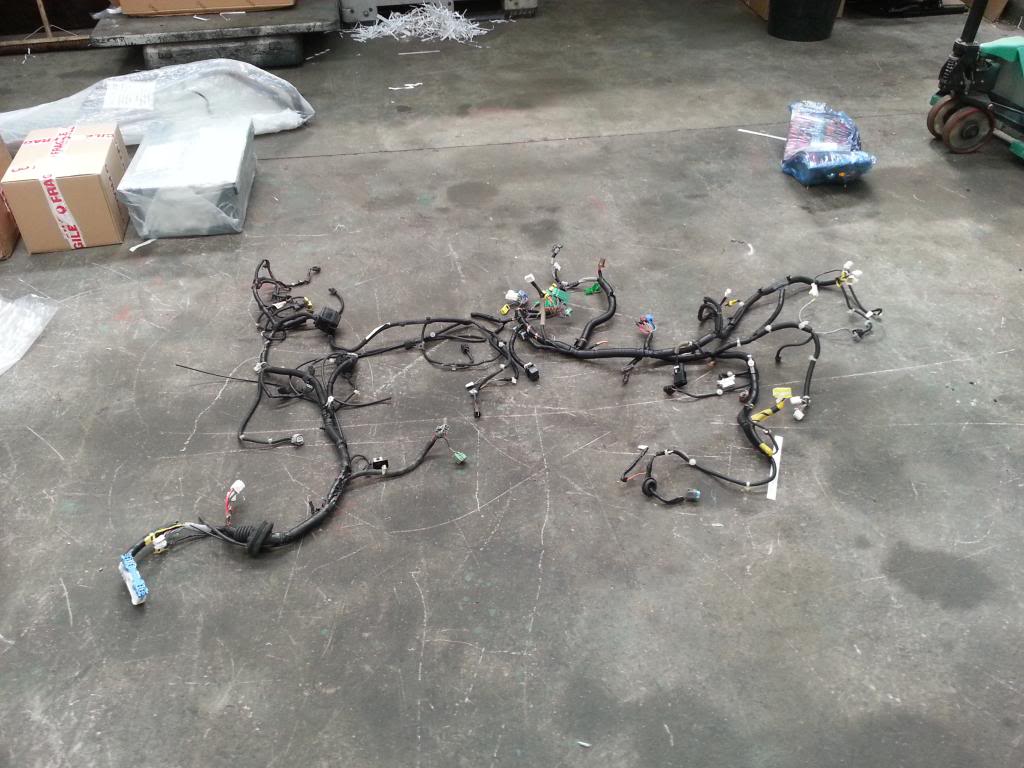
Before sourcing anything, confirm which control hardware your car uses: look at the recirculation baffle above the cabin air filter and note whether it hinges at the top or the bottom. The parts listed here suit the top-hinged variant only. Once the donor components arrive, prep the wiring off the car. Take the full EDM interior harness, locate the 36-pin connector that serves the HVAC controls, and unwrap the loom to expose the individual conductors. Using the Jazz service manual schematic and 36-pin pinout, separate out only the wires that belong to the climate system so you end up with a compact, ready-to-install sub-loom rather than the whole car harness. The Jazz sub cord needs no modification.
2 Isolate power and remove the head unit
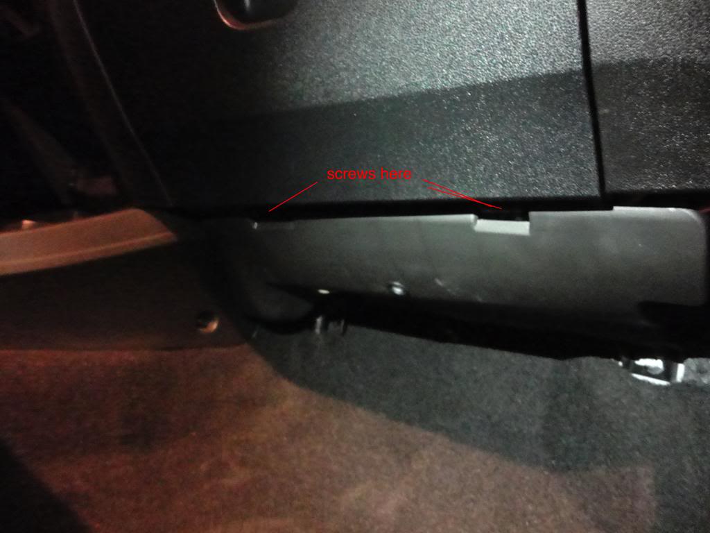
Disconnect the battery first so nothing can short or trigger the SRS while you work behind the dash. Take out the two screws at the base of the lower glovebox, open it fully, and pinch its side walls inward to release it. Pry the lower center console trim loose along its bottom edge to free the clips, then draw it downward to clear the upper tabs. Slide the recirculation lever to the right to expose the bolt beneath the radio; you can sight it through the glovebox aperture. Remove that bolt, open the upper glovebox, and pop the head unit out through the small slot. Ease the assembly forward and unplug it, noting where each connector belongs.
3 Remove the factory manual controls
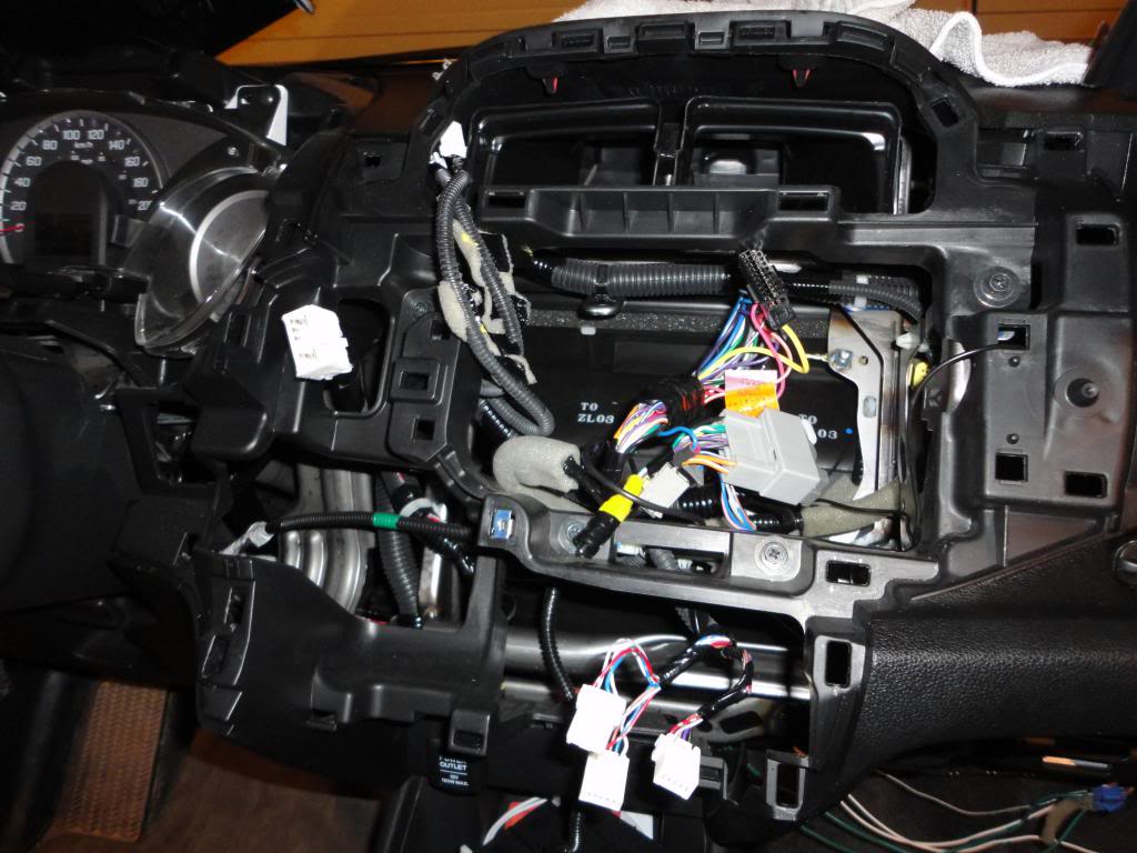
Free the three control cables before the panel will release. Turn the mode knob fully counterclockwise to vent and unclip its cable from the lever and holder. Move the fresh/recirculate lever to recirculate and release that cable the same way. Set the temperature dial to full cold and detach the air-mix cable. Remove the gauge cluster surround so the control panel can clear, take out the single screw at its front center, and gently work the panel free; the three lower clips break easily. Unplug the connectors and withdraw the panel together with its pulley cables. You now have the complete manual assembly out for side-by-side comparison with the automatic unit.
4 Remove the heater blower assembly
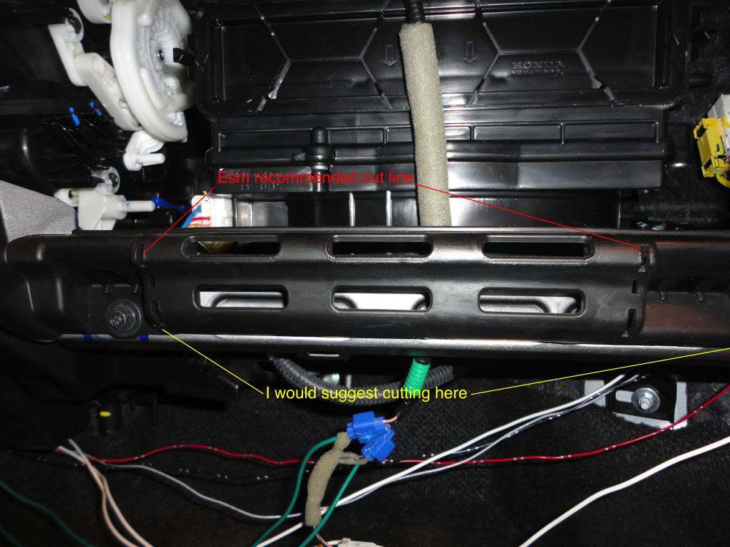
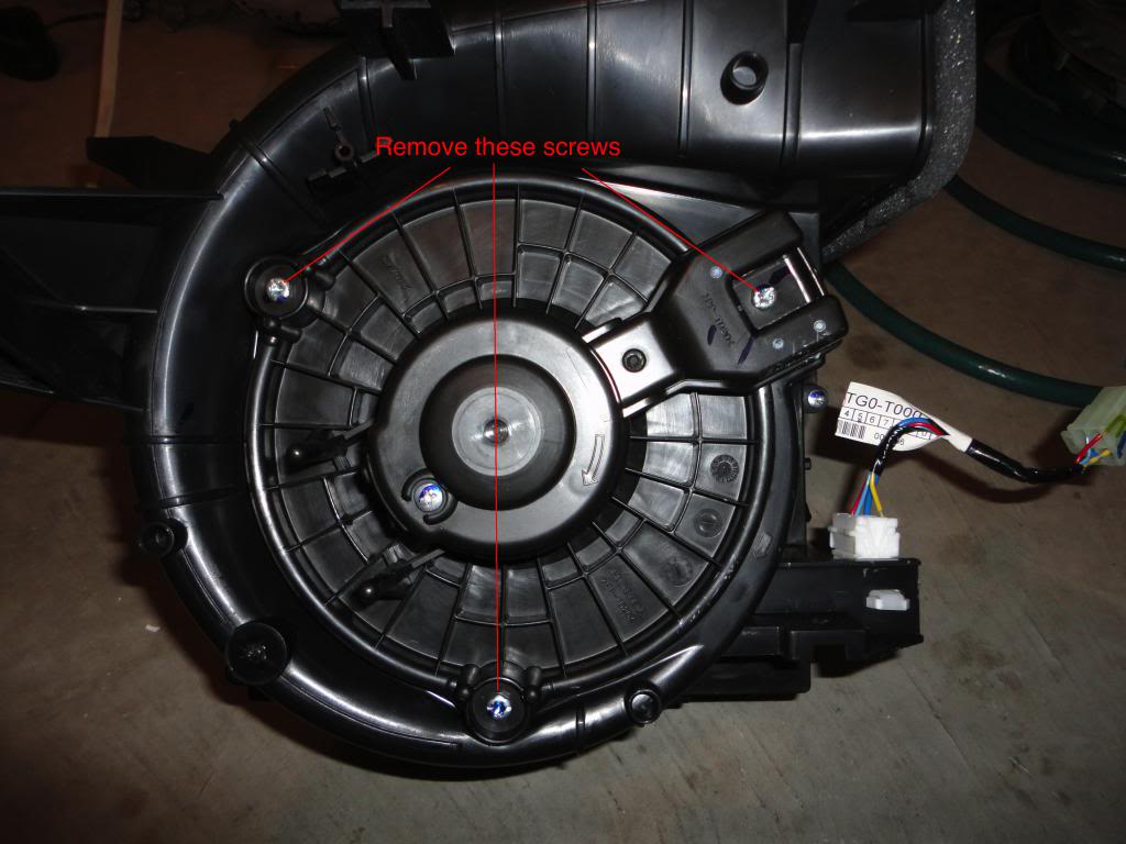
Keep the service manual open for this stage. Drop the passenger-side under-dash cover, then cut the plastic brace at its two marked points; cutting slightly wider than indicated gives the blower more clearance on the way out. Undo the metal support (five bolts), unplug the blower motor and its resistor, and remove the lower left vent (three screws). Take out the two screws and three bolts holding the blower, catching the bolts so they do not vanish behind the carpet, and draw the unit clear.
5 Fit the servo motors and power transistor
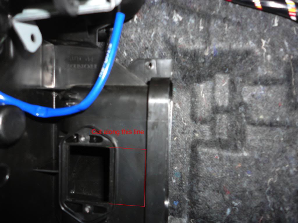
Unscrew and withdraw the factory blower resistor (two screws). Widen its opening sideways to accept the power transistor, which shares the resistor's height; seat the transistor in the enlarged slot and tape the edges, since a snug fit holds it without screws. Swap the outer air-mix lever for the new one (single screw) and grease it, then grease the inner tracks of the replacement round selector piece. Remove the old mode-selector round piece without disturbing the levers beneath, and take off the lever the cable used to drive. Move the air-mix lever through its full range to confirm it runs freely, then trim or drill away the lower part of the cable holder so it no longer fouls the new lever. Screw the air-mix motor to the existing mount and link its arm to the lever; set its pivot by aligning the base of the connector opening with the top of the cable holder, then back up the unsupported upper-rear corner with a stack of 3M VHB tape. Mount the mode motor on its single existing boss, where it self-locates, and secure its two remaining mounts to the air-box side with more VHB stacks. Check every lever sits in its track, but leave the harness unplugged for now.
6 Solder the control wires into the vehicle harness
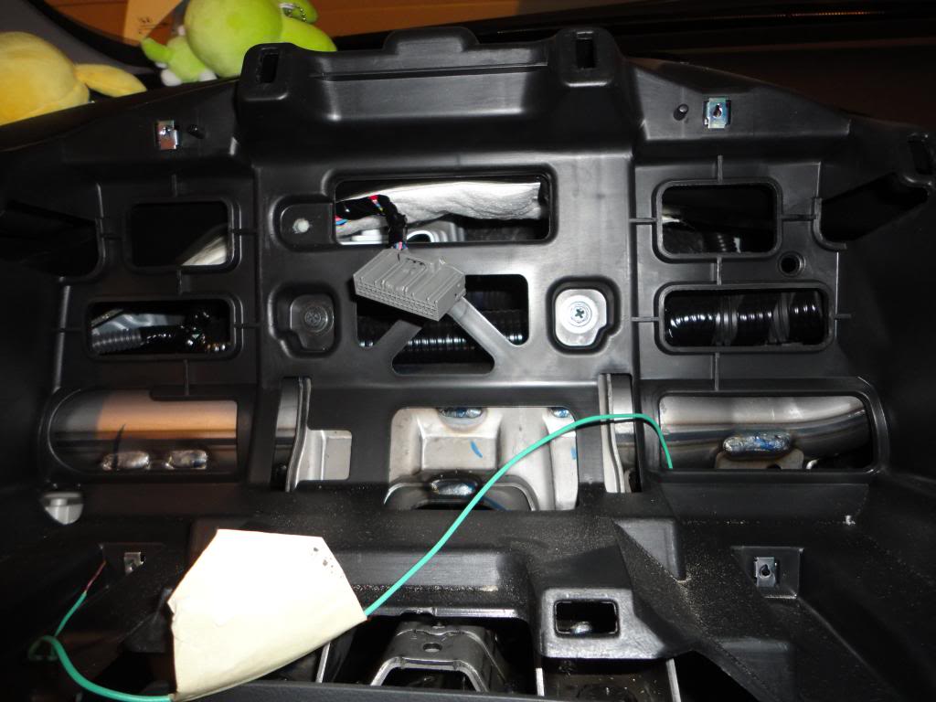
Ten wires from the new loom tie into the car; solder every one and insulate it, and never use quick-tap connectors. Strip about a half inch of the target wire, part its strands with a pen tip, thread the new bare wire through, twist it around the strands, then solder and tape. The colors match the factory wiring except where noted. Splice the light-green conductor into the B-CAN network at pin 18 of the connector behind the gauge cluster (remove the cluster's four screws to reach it, then refit it). Join the grey wire to ILL+, the blue wire to the A/C circuit, the brown wire to IG2, and the purple wire to the window/mirror defog, all on the original harness. Connect the thick black wire at the fan-speed control harness, the thick white wire at the blower motor connector, and the thin black wire to the existing ground. The one exception is the black ILL- wire: run it to the red dash-dimmer wire (pin 1 of the larger harness, pin 5 of the smaller), because the EDM car lacks dimming so those colors do not correspond. Finally, take the orange wire to the evaporator temperature sensor wire at the heater box. Gather and tape the leftover slack so nothing can snag later.
7 Install the interior temperature sensor and aspirator
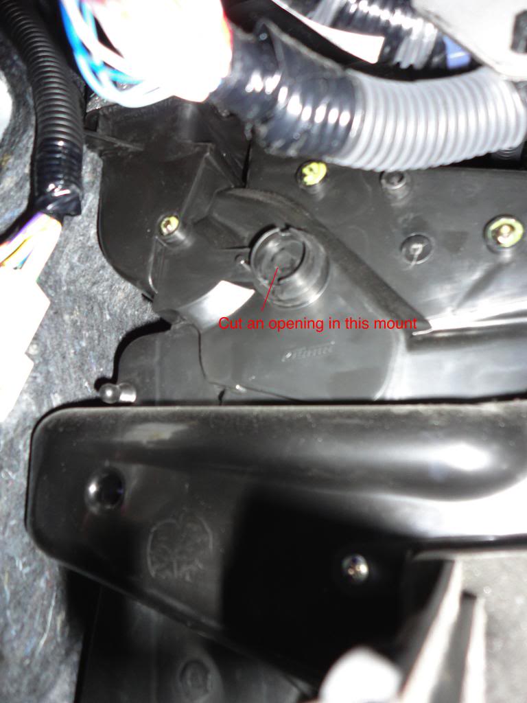
Remove the driver-side lower cover. Cut a hole about the size of a quarter at the aspirator template on the heater unit and fit the aspirator and its hose to the box. Route the hose up to the sensor location behind the small grille in the cluster surround, pass the connector through the same opening, join the sensor to both the hose and the harness lead, and press it in until it clicks home.
8 Install the sunlight sensor
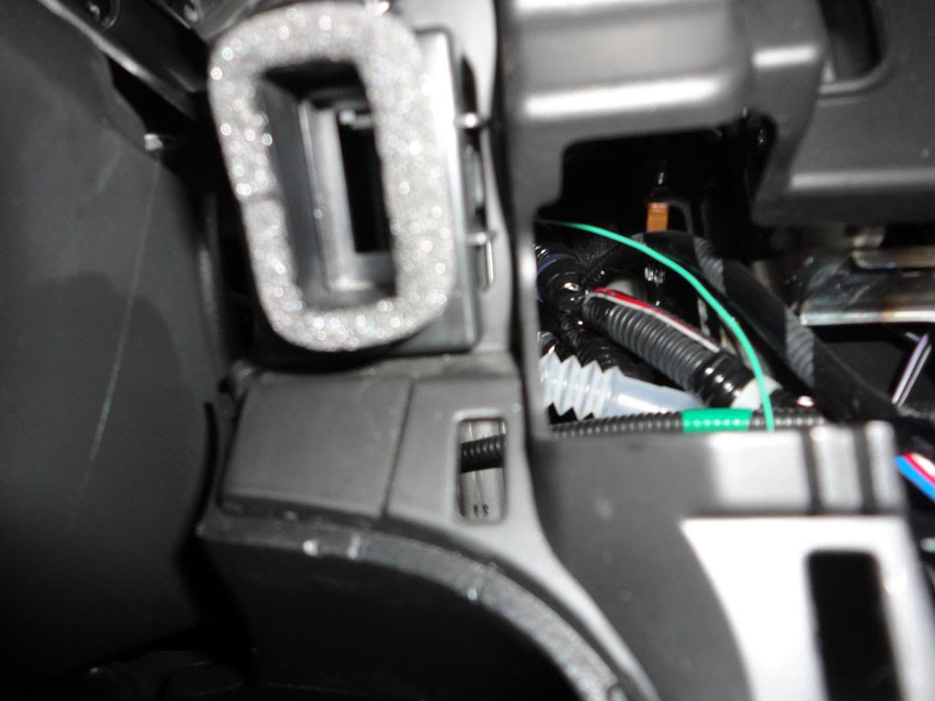
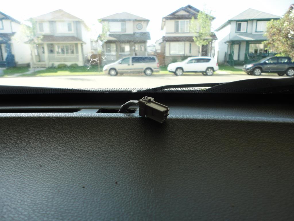
Cut the small rectangle in the passenger-side dash top near the windshield. The plastic runs about 3mm thick with roughly 1.5cm of clearance beneath, so use a fine blade such as an exacto knife and a light touch to avoid damaging anything below. Connect the sensor's short lead to the harness before feeding it through; pulling a guide wire down from above and drawing the harness up makes the awkward routing manageable. Clip the sensor into the opening.
9 Install the outdoor temperature sensor
Pass the sensor wire through the passenger-door grommet and run it behind the passenger fender. Take off the upper grille cover and route the lead to a point just ahead of the radiator. Clip the sensor to its connector and onto a mounting hole, then run its opposite end into the main harness, and tie the lead to existing looms so it stays put.
10 Rebuild the blower box and connect the sub-harness
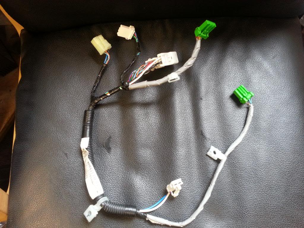
Move the blower motor to the new blower box (three screws) and transfer the air filter and its tray. Fit the fresh/recirculate motor to the new box (three screws), making sure its arm engages the lever, and grease the lever. Confirm the blower motor seals cleanly to the box. Plug the prepared sub-harness into the soldered-in main loom, then join the air-mix motor, the mode motor, and the transistor; the remaining plugs go in later. Tidy and secure any slack.
11 Refit the blower box
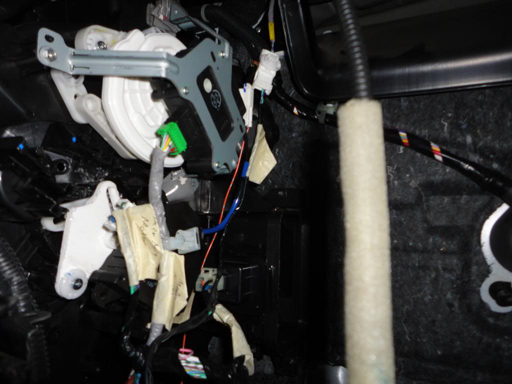
Reinstall the new blower box by reversing the removal sequence in the service manual. Seat and fully seal the left side vent first, since everything else references off it. Holding the unit in place, start the three bolts and two screws by hand before tightening to avoid dropping them, then plug in the blower motor and fresh/recirculate motor, leaving the old blower connector unused, and allow enough cable slack. Refit the floor vent (three screws) and the metal bracket (five bolts) with its cover, and check that no wire is pinched or obstructing servo travel.
12 Fit the control unit, power up, and run diagnostics
Plug the 36-pin connector into the automatic control head and clip it into the dash, starting with the three lower clips and working upward while keeping the cables behind from bunching. Fit the single front-center screw, then refit the cluster surround and the driver-side under-dash cover. Reinstall the radio by reversing its removal, leaving the lower glovebox out for now. Reconnect the battery and tighten its terminal. With the glovebox still off, verify the servos move smoothly and do not stall, then run the self-diagnostic and sensor-input tests from the service manual and address any faults it reports. Once everything checks out, close up the dash and covers.
Pro Tips
- 💡 Most of the soldering happens on the bench rather than in the car, so it is more approachable than it looks; a good pair of wire strippers does most of the work.
- 💡 Sourcing is the hardest part. Search UK car breakers for used pieces, try the Swedish site bildelsbasen.se for the control unit, and use Lings Honda for any new parts; the bulk of the components have to come from Europe.
- 💡 A Jazz Hybrid unit gives the display color closest to the stock cluster. European displays read in Celsius, and only the Fit EV unit shows Fahrenheit.
- 💡 The mirror and rear-window defog turn off automatically after an interval that varies with outside temperature, staying on continuously when it is very cold.
- 💡 If the compressor cycles on and off erratically, check the blue A/C wire for a loose solder joint and run the self-diagnostic and sensor-input tests before suspecting anything else.
Was this guide helpful?