
Honda Accord Euro (CL9) Center Console and Switch Backlighting LED Color Conversion
- The audio/climate console lamp supply is 6 V, not 12 V - resistor values calculated for 12 V will leave the console LEDs dim, and omitting resistors will burn LEDs out. The other switches (seat heater, hazard, VSA, sunroof) are on 12 V.
- The original author noted that polarity may be marked incorrectly on one of his diagrams - confirm correct LED polarity yourself before soldering.
- Remove only one clear diffuser segment at a time; if the buttons and reflectors fall out it is nearly impossible to work out how they go back.
- Work gently when levering trim and do not force knobs or the window-lock button off - replacement switch gear from Honda is expensive.
Introduction
This conversion replaces the stock green backlighting of the Honda Accord Euro (CL9, 2003-2005 Australian-market Accord Euro) interior controls with LEDs in the colors of your choice - the original build used white with red accents. It covers the entire audio/climate center console, VSA and sunroof switches, seat-heater switches, hazard switch, driver's door window/mirror/lock control panel, and the passenger and rear window switches. The factory illumination uses soldered-in surface-mount lamps, so this is a desolder-and-replace job on multiple PCBs requiring fine SMD soldering skills, correct resistor selection, and careful attention to LED polarity. Beyond the color change, LEDs (rated around 100,000 hours) are a permanent fix for the CL9's notoriously hard-to-replace blown console backlight globes. Adapted from a community writeup by EUR003act on OzHonda (https://ozhonda.com/forum/showthread.php?71765-DIY-Accord-Euro-Centre-Console-Lighting-Colour-Modification), including corrections from the follow-up discussion.
Procedure
14 steps-
Step 1: Remove the gear boot surround and ashtray assembly
Open the cigarette-lighter compartment, remove the ashtray, and remove the two screws underneath it. Remove the gear boot surround (manual transmission described): hook your fingers inside the leather under the edge of the plastic and pull up - four clips, one in each corner, hold it in. With that out, unclip the entire cigarette-lighter/ashtray piece in the same manner, lifting it up while angling it slightly outwards.
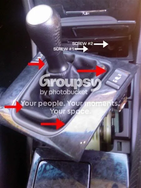
FIG. 2.1 -
Step 2: Remove the cargo compartment and lower fasteners
At the bottom of the center cargo compartment remove the two or three screws, open the door, grab both sides and pull directly towards you to unclip it, then close the door and wiggle the unit out. Store it safely - it is not needed again until reassembly. Underneath the console unit, remove the two silver hex screws now visible, noting the auxiliary connection for the head unit.
-
Step 3: Lever off the center console top panel
This is the fiddliest stage, so proceed cautiously. Wrap a soft cloth around the paint scraper to make a non-marring lever. Slip it in above the radio, in the join where the console top plate meets the dash, and very carefully lever up to release the front three clips. With those released, the panel slides rearwards (towards the car's back) to free the remaining four clips. Then unclip the hazard light switch and the sun sensor, free the wiring from its two retaining clips, and set the panel somewhere safe.
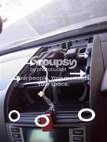
FIG. 2.3 -
Step 4: Remove the radio/climate control unit
Undo the three screws along the top edge of the radio/climate control unit. The unit is now free: pull it out, unclip the three cable connectors on the back plus the cable clips, and take the whole unit to your soldering bench.
-
Step 5: Remove the seat heater, VSA and sunroof switches
Seat heaters: gently rotate and pull down the leather boot to unclip it from the gear knob, unscrew the gear knob counter-clockwise, and lift the boot together with its surround off the shaft. Turn the surround upside down, remove the top two screws holding the boot in its holder, then the two screws holding the switches on each side, and push the switches out from the rear. VSA/sunroof: slide a fingernail (or carefully a small flathead) under the plastic surround holding the VSA, sunroof and blank plate - levering from the bottom is easiest - and unclip it. Disconnect the wiring, then push in the clips on the top and bottom of each switch and slide it out.
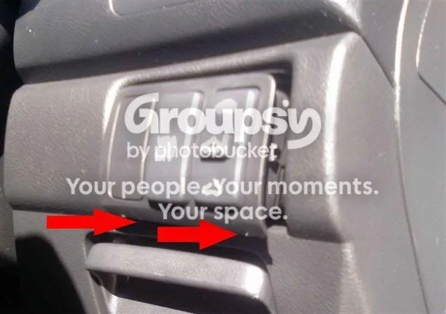
FIG. 2.5 -
Step 6: Remove the door switch panels and extract their PCBs
Driver's door: unclip the patterned surround around the switches by lifting from inside the door handle recess - there are two main clips, one at the very front and one at the rear - and slide it out. Unclip the cables, place the unit upside down (protect the mirror controls), remove the six or seven screws on the back, separate the controls from the top panel, and unclip the plastic backing plate with a flathead to expose the PCB. From the front, gently lift off the window-lock button (do not force it), remove the tiny Phillips screw inside the top black plastic square with the jeweler's screwdriver, and the PCB comes out easily. Passenger and rear doors: remove the surrounds the same way, disconnect the cable, flip each unit over, unclip the blue cable socket along with the square backing plate, and the PCB drops out into your hand.
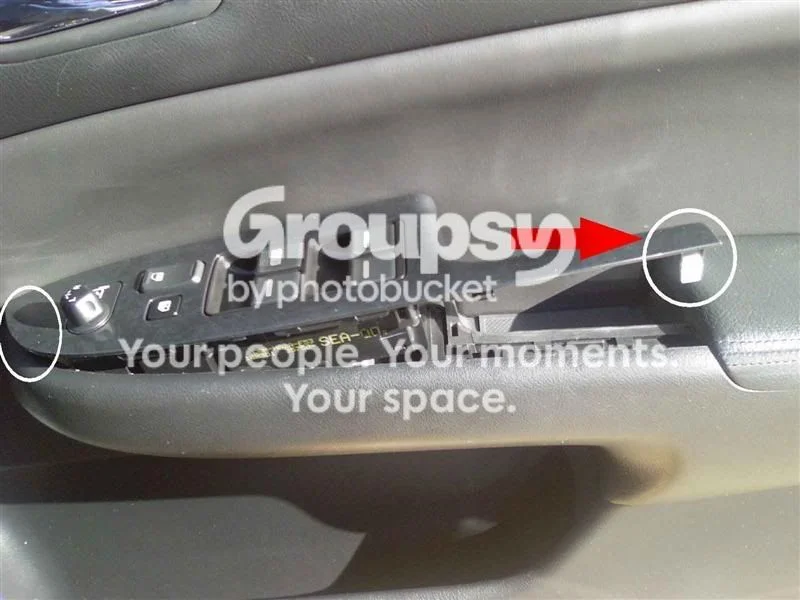
FIG. 2.6 -
Step 7: Disassemble the radio/climate console
This is the time-consuming part. Undo the six large screws holding the CD player and lift the entire player straight up off the panels - it is connected only by two surface-mount sockets, so do not bend any pins. Undo all screws on the back of the main PCB, noting where each goes; unscrew and unclip the topmost plastic panels first, then the underlying PCBs. Once every screw is out (not forgetting the pair that secure the black plastic CD guide), turn the assembly over and pull off the volume, temperature and passenger knobs - a fingernail slipped underneath levers them off (each knob also has two retaining screws, so check these are removed if a knob resists). Take out the PCB to expose the back of the console, and separate the climate-control button board by unclipping the vanilla-colored clip found where the ribbon cable ends, leaving two separate boards.
-
Step 8: Desolder the OEM lamps
Desolder the original surface-mount lamps on each PCB, using the long-nose pliers or tweezers to pull the globes off as the solder melts. Be very careful not to ruin the solder tracks - the new LEDs solder onto the same pads. On the door-control boards the factory lamps may also be glued down (done at the factory to aid soldering), so expect them to be slightly stuck and use the needle-point tweezers.
-
Step 9: Work one clear diffuser segment at a time and frost the LEDs
On the center panel back plate (buttons facing down) there are three separate clear panels. Remove only ONE segment at a time by undoing only that segment's two screws - if you bump the unit with more open, the buttons and reflectors fall out and are nearly impossible to refit correctly. Because LEDs are far more directional than the original lamps, sand each 3mm LED with the fine sandpaper until it is no longer clear and looks like a frosted globe; this distributes the light evenly across the panel.
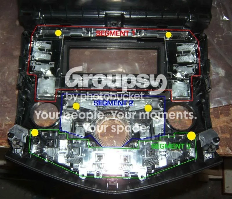
FIG. 2.9 -
Step 10: Calculate resistor values and plan component placement
The audio/climate console backlight supply is 6 V, not 12 V - calculate resistors accordingly. Use: R = (V - Ve) x (1000 / vf). Here R stands for the resistance in ohms, V is the base voltage (6 V for the audio/climate console, 12 V for the other switches), Ve is the LED forward-voltage drop (usually 2-3 V) and vf is the LED current in milliamps (typically 20-50 mA). Worked example: 133 = (6 - 2) x (1000 / 30). The original build used 1% 0.5 W resistors, though 5% 0.25 W resistors should be fine for most LEDs. Before soldering each LED, place the clear segment over the PCB in its assembled position and check the clearance around each lamp point to decide where the resistor will sit without fouling anything; re-check after soldering.
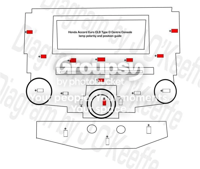
FIG. 2.10 -
Step 11: Solder the LED and resistor pairs onto the console PCBs
Solder each LED and resistor pair in place, observing correct polarity per the circuit diagram - and note the original author's correction that polarity may be marked backwards on one of his diagrams, so confirm polarity yourself with a multimeter before soldering. The LEDs that sit inside the rotary dials (LP18, LP12 and LP19) must be mounted standing vertically so they fit within the knob housings. Then do the bottom PCB containing LP203, LP202 and LP207 (these light the lower climate-control settings) in the same way, continually checking clearance against the clear plate.
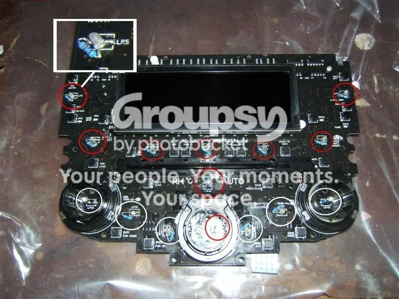
FIG. 2.11 -
Step 12: Bench-test the console LEDs in the car
Before screwing everything back together, test the LEDs using the CD player unit together with the main PCB. Carry both out to the car and plug in the CD unit's socket (the one on its own cable) - the other two connectors are not needed. Then align the control PCB with the plugs on the CD player's front face and press the two together gently, never forcing them. Turn on the parking lights and check every LED lights. Then refit the clear segments, screw the PCBs back into their positions, and refit the knobs and dials, lining up the center piece correctly. The eight short screws belong in the holes that the board marks with a white circle; the longer screws fill every other hole. Refit the two plastic covers, then the CD player on top, aligning the plugs and sockets carefully.
-
Step 13: Convert the door switch PCBs
Desolder the OEM lamps from the door boards and fit the new SMD LEDs - no resistors are needed here, as the nominal voltage at the OEM LED positions is only about 1.8-2.5 V. Pay attention to polarity per the diagram (and verify it yourself). The driver's door uses slightly larger SMD LEDs (about 2.5 x 2 mm) than the other doors, but standard white SMD LEDs work in all positions. For the right-angle 3mm lamp that lights the mirror controls, sand a normal 3mm LED and bend its legs to fit, checking against the mirror-control housing before reassembly. To test, plug the PCB in and switch the car to ignition; when testing the passenger or rear controls, the main driver unit must also be plugged in and the window lock switched OFF. Central locking will not work with the driver unit disconnected - the central-locking brain and RF antenna live in the driver control panel.
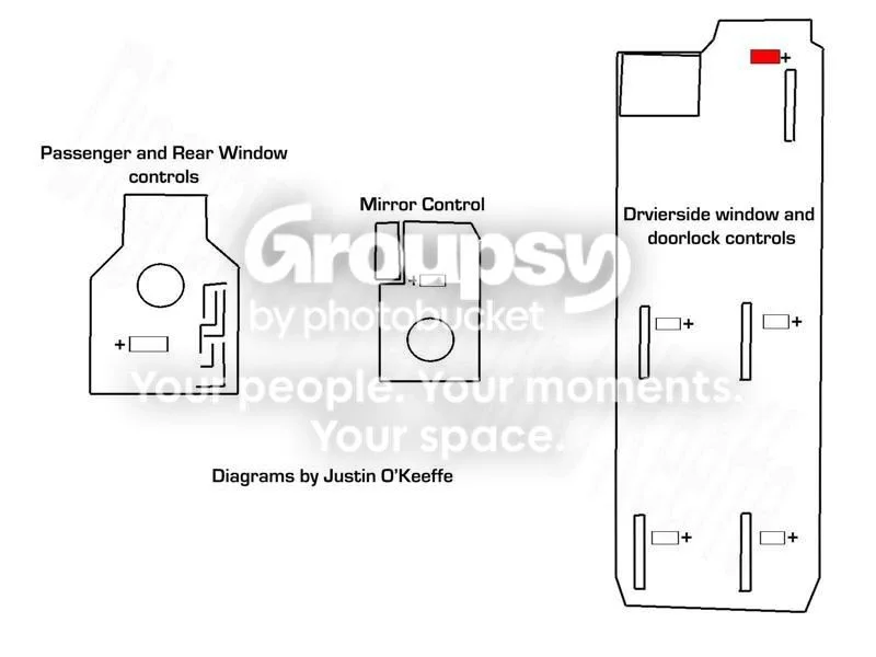
FIG. 2.13 -
Step 14: Convert the seat heater, hazard, VSA and sunroof switches and reassemble
These are simpler: twist each globe holder anti-clockwise with the flathead screwdriver to remove it (the bulb exits through a hole in the switch unit's side), unwind the wire from around the holder and pull the globe straight out. Sand a new LED to frost it, then fit the LED and resistor - the supply here is 12 V, so recalculate the resistor - pushing the legs through the holes in the holder and wrapping them around the base exactly like the original globe. Unclipping the front button can make this easier (there are two clips at each end of the switch), letting you position the LED inside the housing with pliers. Do not forget the hazard switch backlight. Finally, reassemble everything in reverse order. This is also a good time to replace the cigarette-lighter ring and ashtray globes - they are standard T5 mini wedge globes.
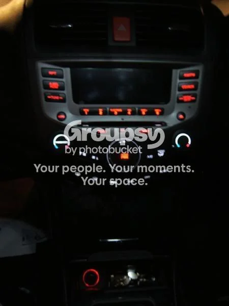
FIG. 2.14
- A cheap soldering iron makes this job much harder - its temperature fluctuates and the tip is too big for SMD work. The original build used a Goot 13 W temperature-controlled iron with a very fine tip (about $40 from Jaycar).
- White SMD LEDs can be sourced by buying an LED replacement globe that contains 12 white SMD LEDs (Jaycar ZD0485, about $30) and harvesting them - spares included for mistakes.
- Any LED color works; ultraviolet was trialed but 5mm UV LEDs looked too spaced out in the 3mm positions without extra modification.
- Soldering technique: heat the pad, flow the solder to liquid, attach the LED contact in the correct polarity, add solder as needed and let it cool solid.
- This conversion doubles as the permanent fix for the CL9's common dead center-console backlight, since LEDs last around 100,000 hours.
Related procedures
All guides →
Tap right for next · left for back · Keys: ← → step · Space / PgUp / PgDn scroll · Esc exit