Building a K-Series Swap Conversion Wiring Harness for the Honda Civic (EG)
Introduction
This guide covers building a custom K-series swap wiring harness for a 1992-1995 Honda Civic (EG) chassis, letting you integrate an RSX-based K20 engine and ECU without paying for a pre-made plug-and-play harness. The approach reuses two salvaged connectors - the C101 that mates to the K-series engine harness and the E-plug that feeds the ECU - plus three relays, and taps a short list of switched, sensor, and power circuits into the car's original ECU connector. Beyond the cost savings, the real payoff is a thorough understanding of how the swapped engine interfaces with the chassis electrically, which makes future troubleshooting far easier. The same core method has been adapted by the community to EF/CRX, EK, and DC2 chassis, though those cars use different main relays and cluster signals and require their own verification. Work slowly, label every wire, and confirm each connection with a multimeter before the first start. Adapted from a community writeup by kazino42 on K20A.org (https://www.k20a.org/threads/simple-wiring-harness-write-up-for-eg.11966/), including corrections from the follow-up discussion.
Reference
Tools Required
- Hondata K-series wiring schematic and a factory (Helms) service manual
- Wire crimping tool with OEM-style terminal pins
- Terminal depinning tool (a straightened, filed paperclip also works)
- Digital multimeter
- Soldering iron, solder, and heat-shrink tubing
- Wire strippers and cutters
Parts Required
-
RSX sub-harness (or a 2002 Civic sub-harness) to salvage the C101 and E-plug connectors
-
Three relays (salvaged stock relays or universal relays)
-
30 A fuse to replace the 7.5 A underhood battery-feed fuse
-
Data link connector (DLC)
-
Automotive wire in the required color/stripe combinations
-
Assorted terminal pins and heat-shrink
Safety Warnings
- ⚠ Verify every connection with a multimeter before the first key-on. A single mis-pinned wire can damage the ECU or K-Pro unit.
- ⚠ When wiring the battery-positive circuit (D1), replace the 7.5 A underhood fuse with a 30 A fuse; an undersized fuse will fail under load.
- ⚠ A missed ground or mis-wired pin commonly throws a VBU (voltage backup) code and can indicate a fault serious enough to harm the ECU - trace grounds carefully before applying power.
Step-by-Step Instructions
1 Source the connectors and reference documents
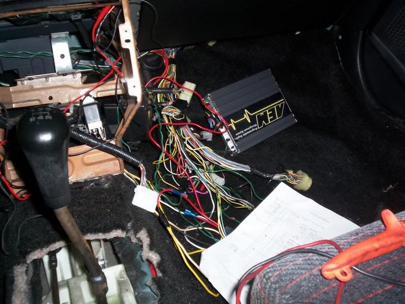
Rather than buying a plug-and-play conversion harness, build your own from salvaged connectors. The two you must obtain are C101 (the interface to the K-series engine harness) and the ECU E-plug. Both can be cut from an RSX sub-harness; a 2002 Civic sub-harness also works and lets you reuse its stock relays, but that connector is missing a few circuits you will need to add by hand. Keep the Hondata K-series wiring schematic as your primary reference and a factory service manual alongside it - the schematic omits the secondary O2 sensor and the DLC, both of which are documented in the manual.
2 Assemble the harness with its three relays

Build the conversion harness so C101 feeds the engine harness on one end and the E-plug feeds the ECU on the other, with three relays wired in per the Hondata schematic. You can use the salvaged stock relays or generic universal relays. Lay everything out and label each wire before crimping; a clean, planned layout is what keeps the pin-by-pin work that follows manageable.
3 Repurpose the EG main relay socket
The factory main relay is no longer needed, so unplug it and reuse its socket as a junction. Bridge terminals 7 and 8 to route the fuel-pump relay output to pin A7 of the stock ECU connector. Bridge terminals 3 and 5 to route the ignition signal to pin A25. The socket is arranged as two rows - bottom row 7, 5, 3, 1 and top row 8, 6, (empty), 2 - and each terminal maps to a function as follows: terminal 1 is Bat+, terminal 2 is GRN, terminal 3 is A25, terminal 5 is IGN, terminal 6 is the St switch, terminal 7 is Fuel Pump, and terminal 8 is A7.
4 Land the core power and signal wires at the ECU
Bring the three essential circuits into the stock ECU harness: fuel pump on A7, ignition signal on A25, and battery positive on D1. Before energizing anything, swap the underhood fuse feeding the D1 battery circuit from 7.5 A to 30 A so it can carry the load.
5 Tap the remaining E-plug body signals
Route the secondary signals from the ECU E-plug into the stock ECU connector and gauges: E15 (ELD) to D10, E22 (brake switch) to D22, E26 (RPM) to the tachometer, and E31 (MIL) to A13. Note that some builders find the MIL circuit is already carried through the retained B-series plug, in which case E31 does not need a separate wire.
6 Connect the engine-harness accessory wires
From the K-series engine harness, land the accessory and sensor circuits: pin 3 (VSS) to the speedometer/gauge, pin 7 (FanC) to A12 on the stock ECU connector, pin 8 (Alt-L) to A16, pin 16 (starter) soldered to the ignition or spliced to the starter wire, and pin 18 (oil pressure) to the gauge. The VSS can instead be tapped straight from the instrument cluster, which supplies a compatible speed signal.
7 Wire the data link connector (DLC)

The DLC is absent from the Hondata schematic, so wire it from the service manual pinout. Connect pin 4 (BLK) to chassis ground; pin 5 (BRN/YEL) to logic ground LG3 at ECU pin E3; pin 7 (LT BLU), the K-Line (2-way serial), to ECU pin E23; pin 9 (BRN), the service check signal, at ECU pin E29; pin 12 (RED/WHT), the write-enable line, to ECU pin E30; pin 14 (GRAY), +5V, to immobilizer control unit pin 3; and pin 16 (WHT/RED), +12V, from the 7.5 A backup fuse. As a shortcut for reading blink codes, grounding ECU pin E29 will trigger the CEL flash sequence.
8 Wire the secondary O2 sensor
Wire the secondary (post-cat) O2 sensor plug, which the Hondata schematic also leaves out. Its four terminals map as follows: terminal 1 to E2 (WHT/RED, SHO2S); terminal 2 to E4 (PNK, SG3); terminal 3 to the A/F (O2 heater) relay, sharing the primary sensor's supply; and terminal 4 to E6 (BLK/WHT, SO2SHTCR). If you run K-Pro, some builders skip the secondary sensor entirely.
9 Match the harness to your specific ECU
The fuel-pump ground pin differs by ECU. A USDM RSX Type-S PRB ECU grounds the fuel-pump relay through E1 at the E-plug, while a JDM Type R PRC ECU uses E10. If you run a PRC, move that pin from E1 to E10. Also confirm the main-relay ground path: E7 at the E-plug supplies the switched ground that energizes the main relay once the ECU detects ignition on E9.
10 Wire the temp/fan switch, verify, and start
Finally, wire the coolant temperature sender and the radiator fan switch. Before the first start, check every circuit end-to-end with a digital multimeter - this is the single best defense against a wiring mistake that could damage the ECU. With everything verified, the engine should start and run with no check-engine lights. Builders who triple-checked their harnesses consistently report clean, CEL-free startups.
Pro Tips
- 💡 Buy wire in the exact color/stripe combinations the schematic calls for; one UK supplier sells all the striping combinations by the meter, and a full harness's worth of wire ran roughly $40 shipped.
- 💡 You do not need a factory depinning tool - a straightened, filed paperclip works fine for releasing terminals.
- 💡 If the MIL (E31) or fuel pump (E-plug pin 1) already connect through the retained B-series plug, do not run a second wire for them or you will double up the circuit.
- 💡 Building the harness yourself pays off later: you will know exactly how the engine ties into the car electrically, which makes diagnosing problems far quicker.
Was this guide helpful?
