Wiring DSM Low-Impedance Injectors into a Honda D-Series with Inline Resistors
Introduction
Upgrading a Honda D-series engine to larger fuel injectors is a common step when adding boost or other airflow modifications, because the factory saturated injectors eventually run out of capacity. A popular budget choice is a set of 450cc low-impedance injectors pulled from a first- or second-generation DSM (Mitsubishi Eclipse/Talon). Because these are peak-and-hold (low-impedance) units and most Hondas are wired for high-impedance saturated injectors, they need extra resistance added to the circuit. Rather than buying a plug-in resistor box, this guide splices an inexpensive inline resistor into each injector signal wire, a job that costs only a few dollars in parts and takes about an hour. It covers preparing the injectors, fitting their O-rings to the D-series manifold, finding the correct wire at the injector power connector, and soldering the resistors in place. Note that cars already fitted with a factory resistor box (for example 4th-generation MPFI and certain SI models) can often run these injectors without this modification, and any injector change should be followed by ECU tuning. Adapted from a community writeup by Bizzar on D-Series.org (https://www.d-series.org/threads/diy-dsm-injector-and-resistor-wiring-install-pics.7216/), including corrections from the follow-up discussion.
Reference
Tools Required
- Soldering iron
- Rosin-core, acid-free solder
- Soldering flux (optional but helpful)
- Multimeter with continuity/resistance range
- Wire cutters and strippers
- Hobby or pocket knife
- Bench grinder or Dremel with drum-sander bit
- Heat gun or lighter (for heat-shrink)
- Zip ties
Parts Required
-
4x DSM 450cc low-impedance injectors (first-gen blue-top or second-gen black-top)
-
4x 10 ohm 10 watt inline resistors
-
Heat-shrink tubing
-
OBD1 or OBD0 injector clips (if the car is OBD2 or clips need swapping)
-
Small project box for mounting the resistors (optional)
Safety Warnings
- ⚠ Gasoline at the injectors is pressurized. Turn the key to on and check every seat and joint for leaks before starting, and keep sparks and open flame away from the fuel system.
- ⚠ Larger injectors require ECU tuning. Running them without adjusting fuel management can cause a lean condition that damages the engine.
- ⚠ Use only rosin-core, acid-free solder. Acidic or corrosive solder will corrode the connections over time and cause intermittent injector faults.
- ⚠ Do not let an O-ring tear during fitting; a damaged seal causes a vacuum and fuel leak at the manifold.
Step-by-Step Instructions
1 Choose injectors and confirm your car needs added resistance
Source a set of four 450cc DSM injectors; both the first-generation blue-top and the newer second-generation black-top versions work equally well here. Expect to pay roughly $40-75 for a used set. These are low-impedance (peak-and-hold) injectors and draw more current than the high-impedance (saturated) units a Honda expects. As a rough reference, peak-and-hold injectors measure about 1.7-3.0 ohms while saturated ones measure about 10-16 ohms. If your car already has a factory resistor box, such as 4th-generation MPFI cars or some SI models, the injectors can plug in without the inline resistors described here; otherwise continue with this procedure. Plan on tuning the ECU afterward, since the added flow will otherwise upset the air-fuel ratio.
2 Prepare the injector connectors so the Honda plug fits
Each DSM injector has a small locating tang beside its electrical connector that stops a Honda plug from seating. Trim this tang off with a hobby or pocket knife; it does not need to look neat, only to clear enough material for the clip to snap on. On the harness side, DSM, OBD0, and OBD1 injector clips all mate to these injectors once you shave down the plastic spacers inside the clip. OBD2 clips have a narrower pin spacing and will not fit, so if your car is OBD2, wire in OBD1 injector clips instead.
3 Fit the O-rings to the D-series intake manifold
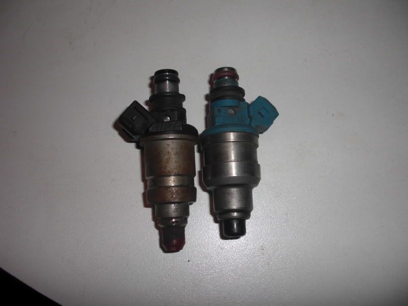
The DSM injector body and its lower O-ring sit wider than the stock Honda parts, so the injector will not drop fully into the manifold seat without adjustment. Two approaches work. Either reduce the O-ring diameter by holding it on the injector (or a similarly round object) and turning it lightly against a grinding wheel or Dremel drum sander until it seats snug and flush, or place each O-ring in the manifold first and let the fuel rail compress the injectors evenly onto them as you tighten it down. Whichever method you use, smear a little oil or grease on the rubber so it does not tear during assembly, then test-fit each injector for a tight, leak-free seat.
4 Locate the injector power connector

Find the injector power connector, often called the dead plug, unplug it, then peel back the wire loom and tape to expose the injector wiring. On 5th-generation cars it sits near the driver-side strut tower; on other generations it may be tucked behind the intake manifold or at the back of the engine, so its exact position varies. This plug is not actually dead: one feed wire supplies 12 volts and an internal jumper distributes that power across the wires to all four injectors (there are five wires here for four injectors, the fifth being the 12-volt feed). OBD2 cars have no dead plug at all, so ignore any reference to it and follow the rest of the procedure.
5 Identify the correct injector wire
Set a multimeter to its resistance or continuity range. Probe the yellow/black wire inside one injector clip with one lead, then touch the other lead to each wire at the power connector until you find the matching pair; the continuity buzzer will sound, or you will read a very low resistance. That is the wire for that injector. Note that with the key on you will typically see power on only one wire at the connector, which is normal, because the resistors (or a factory resistor box) complete the circuit to the remaining injectors.
6 Cut and tin the wire
Cut the injector wire you just identified. Coat each freshly cut end with a thin layer of solder, known as tinning, so it will bond cleanly to the resistor leads. A dab of flux on the strands helps the solder flow and stick. Use rosin-core, acid-free solder only; acidic or corrosive solder will slowly eat the joint and cause intermittent faults.
7 Solder a resistor inline
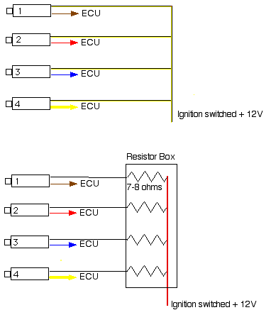
Before making any joint, slide a length of heat-shrink tubing onto each cut end so it stays captive on the wire. Then solder one 10 ohm 10 watt resistor between the two cut ends, bridging the gap in the injector wire. The resistor has no polarity, so either orientation is fine. Keep each joint mechanically solid and fully wetted with solder.
8 Insulate the joints and repeat for all four injectors
Slide the pre-loaded heat-shrink over each solder joint and shrink it with a heat gun or lighter for a moisture-tight seal. Work through the remaining injector wires the same way until all four carry an inline resistor. For a tidy result, gather the resistors into a small project box mounted to the body or strut tower, bundle the wiring with zip ties, and refit the loom. If you expect to swap injectors later, for example at inspection time, add Molex connectors at the ends so the injectors detach without unsoldering.
9 Check for leaks before starting
With everything reassembled, turn the ignition to the on position so the fuel pump primes and pressurizes the rail, then inspect every injector seat and fuel connection for leaks. Start the engine only after confirming there are none. Because the new injectors flow far more than stock, have the ECU tuned before driving to avoid running dangerously lean or overly rich.
Pro Tips
- 💡 If grinding the O-rings is awkward, seat them in the manifold and let the fuel rail compress the injectors onto them instead.
- 💡 A Dremel drum-sander bit sized to the injector fits neatly inside the O-ring, letting you thin it from the inside.
- 💡 Only one wire at the power connector shows 12 volts with the key on; the resistors complete the circuit to the other injectors, so this is expected.
- 💡 Mounting the resistors in a small project box keeps the engine bay tidy and protects the solder joints.
- 💡 Adding Molex or other quick-connectors lets you remove the low-impedance injectors for emissions inspection without cutting wires.
Was this guide helpful?