DIY Flex-Fuel Ethanol Content Analyzer for OBD1 Honda ECUs
Introduction
A factory flex-fuel (ethanol content) sensor from a GM vehicle reports ethanol percentage as a digital PWM signal that swings between 50 and 150 Hz, with fuel temperature carried in the pulse's duty cycle. Most Honda engine management setups, however, cannot read that digital signal directly. Chipped OBD1 ECUs and popular tuning platforms such as Hondata, Neptune, and Honda's tuning suite instead expect a simple 0-5V analog input to interpret ethanol content. Purpose-built commercial converters cost roughly $200. This guide builds an inexpensive alternative for about $20-100 using a junkyard GM sensor and a small Arduino-class microcontroller. The controller decodes the sensor's frequency into an ethanol figure (and its duty cycle into fuel temperature), then re-emits a smoothed 0-5V voltage the ECU can act on, enabling flex-fuel operation on E85 or blended pump gas without constant retuning. It suits boosted or E85 Honda and Acura builds running OBD1 engine management with a chip, Hondata, or Neptune. Adapted from a community writeup by forbiddenera on Honda-Tech (https://honda-tech.com/forums/forced-induction-16/diy-flex-fuel-sensor-ethanol-content-anaylzer-%7E%2420-100-dont-need-zeitronix-3348257/), including corrections from the follow-up discussion.
Reference
Tools Required
- Computer with the Arduino IDE and a USB cable
- Soldering iron and solder (or a solderless breadboard/carrier board)
- Wire strippers and crimp/heat-shrink connectors
- Multimeter for verifying the output voltage
- Small hand tools for mounting and routing wiring
- FTDI/USB-to-serial adapter (only if using a board without onboard USB, such as the Pro Mini)
Parts Required
-
GM flex-fuel (ethanol content) sensor, e.g. part #13577379, or GM 12568450 or 12570260 (flow-through body preferred)
-
Mating sensor connector and pigtail (or a plug cut from a junkyard harness)
-
Microcontroller: Arduino Nano, Pro Mini, Seeeduino Nano, or Mega 2560
-
Two 4.7k resistors (the 0-5V output resistor may be 3.3k or 4.7k)
-
Small capacitor for the RC output filter
-
Inline fuse and holder for the +12V feed
-
Switching buck (step-down) converter to power the microcontroller
-
Optional I2C OLED display for live readout
-
General hookup wire
Safety Warnings
- ⚠ Always fuse the +12V feed to the sensor and controller close to the power source to prevent a wiring short from starting a fire.
- ⚠ A running vehicle's electrical system sits near 14-15V; size the regulator for that and prefer a switching converter to keep the onboard regulator from overheating.
- ⚠ Verify the output voltage with a multimeter and against a known ethanol content before relying on it for tuning; a wrong reading can drive an unsafe air-fuel ratio.
Step-by-Step Instructions
1 Source a compatible GM flex-fuel sensor

Obtain a GM ethanol content sensor that produces the standard PWM output. The build used part #13577379, pulled from a 2013 Impala for about $10 at a junkyard (roughly $65 new). GM 12568450 and 12570260 are equally suitable, and a flow-through body is the easiest to plumb into a fuel line. When harvesting one from a scrapyard, cut the harness leaving a short pigtail of the factory plug attached; if buying new, source the mating connector and some wire separately. Sensor physical size varies between part numbers, so plan mounting accordingly.
2 Choose a microcontroller
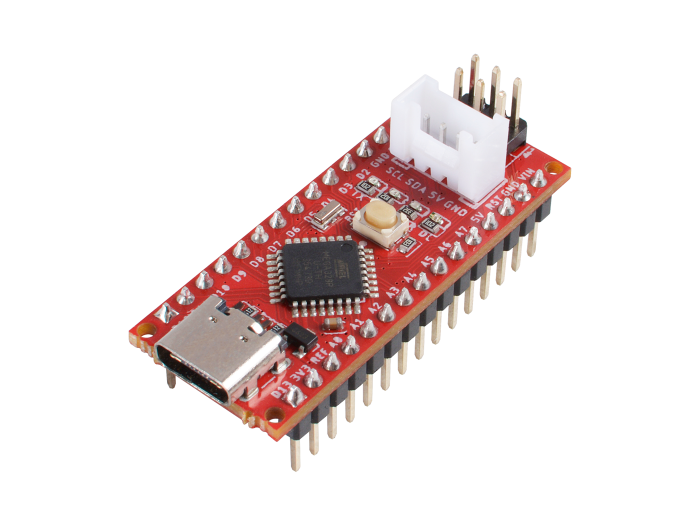
Any small 5V Arduino-class board can do the conversion. A Nano is convenient (onboard USB programming, 1k EEPROM, tolerant of up to 20V in). A Pro Mini is cheaper but needs an external FTDI adapter to program and tolerates up to 16V. A Seeeduino Nano adds an onboard I2C/Grove header that a screen plugs straight into. A Mega 2560 offers far more I/O if you intend the board to handle other tasks as well. Whatever you pick, keep the supply within the recommended 7-12V range to limit heat in the onboard regulator; if the board is doing nothing but the flex-fuel conversion, the smallest and cheapest option is the best fit.
3 Gather the passive and power components
Collect two 4.7k resistors: one serves as the signal pull-up and the other sits on the 0-5V output line, where 3.3k or 4.7k both work. Add a small capacitor to form the RC filter on the output, an inline fuse for the +12V feed, and a switching buck converter to drop vehicle voltage down to a clean supply for the board. A switching regulator is preferred over a linear one because it dissipates far less heat, which matters at the ~14-15V a running car actually produces. Add an I2C OLED only if you want a screen.
4 Wire the sensor power, ground, and signal with a pull-up

Supply the sensor with +12V through the inline fuse and a solid ground. Run the sensor's signal wire to the microcontroller's input, and tie a 4.7k pull-up resistor from that signal line up to 5V. This pull-up is essential: the sensor's open output pulls the line low when it wants to, but without the resistor holding it high there is no usable signal to read. If a relay switches the +12V feed, fuse the current side ahead of the relay and protect the coil side appropriately.
5 Assign the correct firmware pins for your board
Pin numbers differ by board and must match the firmware. On an Arduino Nano the fuel-temperature output lives on pin #10. On a Mega 2560 the sensor signal enters on pin #49 and the ethanol output is on pin #10. The temperature output was originally placed on pin #11, but note the correction from the discussion: the author accidentally damaged pin #11 and moved to Timer5 driving pin #46. Follow that revised assignment and choose a healthy, timer-capable output pin, since the timer used dictates which pin the PWM output appears on.
6 Flash the conversion firmware
Upload the provided sketch to the board over USB using the Arduino IDE (a Pro Mini needs an FTDI adapter for this). The firmware measures the sensor's incoming frequency to derive ethanol percentage and its duty cycle to derive fuel temperature, using hardware timers and interrupt service routines so the measurement never blocks the main loop. This non-blocking design lets the same controller drive a display or handle other jobs simultaneously. Before wiring into the car, confirm on the bench that the readings and outputs behave as expected.
7 Smooth the output into a stable 0-5V with an RC filter

The controller represents ethanol content as a fast PWM output; feed it through a simple resistor-capacitor filter to average it into a steady analog voltage the ECU can read. Bench testing confirmed the PWM is fast enough that this passive filtering yields a perfectly stable output, so a dedicated DAC is unnecessary. Build one filter for the ethanol output and, if you also want fuel temperature, a second identical filter on that line.
8 Power the controller from the vehicle
Feed the board from a fused +12V source through the switching buck converter rather than relying solely on the board's onboard linear regulator. At real automotive voltage (test around 14.8V) a linear regulator runs hot, and stacking a second linear regulator in front of it only relocates that heat. A buck converter avoids the problem. Set the converter's output to a level within the board's recommended input range, or to 5V if feeding the board's 5V rail directly.
9 Connect the output to the ECU and enable flex fuel
Route the filtered 0-5V ethanol signal to the ECU's flex-fuel analog input. Neptune, Hondata, and Honda's tuning suite all accept a 0-5V ethanol input and scale fueling and ignition against it. Before trusting it for tuning, use a multimeter to confirm the controller's commanded voltage arrives at the ECU intact (for example, a commanded 2.5V should read 2.5V at the input). With a platform like Neptune, the same 0-5V value can be displayed as a 0-100% ethanol reading in software, so an added gauge may be redundant.
10 Add an optional OLED display

For a real-time readout without a laptop, connect a small I2C OLED to the controller. A 128x64 monochrome 'widescreen' OLED is a practical choice and stays readable in bright light; larger LCD, e-ink, or touchscreen options exist but add cost, size, or code. On a Seeeduino Nano the display plugs straight into the onboard I2C header, and a 4-pin extension lead lets you mount the screen remotely. This step is entirely optional and can be skipped if your tuning software already shows the ethanol value.
Pro Tips
- 💡 Junkyard sensors are cheap (around $10); a 2013 Impala is one known donor. Cut the plug off with a pigtail attached to save buying a connector.
- 💡 Flow-through sensor bodies are the easiest to plumb; versions with AN adapter fittings are also available.
- 💡 A switching buck converter runs much cooler than a linear regulator and avoids moving heat around by stacking regulators.
- 💡 If your tuning software (e.g. Neptune) can display a 0-5V aux input as a percentage, you may not need a separate screen at all.
- 💡 The high PWM output frequency filters cleanly with a basic RC circuit, so an external DAC is not required for a stable signal.
Was this guide helpful?