
Installing a Tucked K-Series Engine Harness for a K-Swap (Non Drive-by-Wire)
- Check fitment before you start. Hybrid Racing says this harness is not for drive-by-wire engines, K20C or direct-injected K24 engines, or UK-spec narrowband ECUs. It expects a US or JDM ECU running the factory Denso wideband sensor.
- Disconnect the battery before starting and keep it off until the whole install is finished.
- An unfused 12 V cable that shorts can start a fire; fuse the alternator charge cable.
- If you smell burning, see smoke or blow a fuse at key-on, switch off and disconnect the battery before touching anything.
Introduction
A tucked engine harness replaces the OEM K-series engine harness with one that runs closer to the engine, which tidies a swapped engine bay and reduces the chance of chafing. Hybrid Racing's harness is built around 2002-2004 RSX Type-S (K20A2) wiring with Honda wire colours, for engines with a cable throttle running a PRB ECU or K-Pro; it is not for the 2005-2006 RSX drive-by-wire setup. Most connectors simply plug in by label, but engines with K24-style crank or knock sensors need one connector housing swapped. You still need a ground kit, an ECU and a conversion harness for your chassis. Adapted from a community writeup by Hybrid Racing on guides.hybrid-racing.com (https://guides.hybrid-racing.com/Guide/Hybrid+Racing+K-Series+Tucked+Engine+Harness+Install+Guide/591).
Procedure
14 steps-
Step 1: Disconnect the battery and strip the old harness
Disconnect the battery before unplugging anything and leave it off until the end. Remove the old engine harness so every sensor is bare, and decide where the ECU will mount.
-
Step 2: Lay the harness on the engine
Unpack the main harness, injector sub-harness, VSS sub-harness, spare K24 connector housings, two heavy power cables and zip ties. Drape the cabin section over the cowl and lay each branch near its sensor before plugging anything in. Every branch carries a printed label (VTS, OIL, INJ3, TPS, and so on). Branches whose sensors move between the K20 and taller K24 block are deliberately long.
-
Step 3: Connect ECT and both cam sensors
At the transmission end of the head, plug in the coolant temperature sensor (ECT) low on the end face, then cam sensors CMPA and CMPB higher up under the valve cover lip. CMPA and CMPB look alike and sit side by side; mixing them up is a common no-start cause, so match each label.
-
Step 4: Connect the coils and engine ground
Run the coil branch over the valve cover and plug in coils CP1 to CP4, with CP1 at the timing-chain end. Bolt the GND eyelet to the valve cover stud on clean bare metal and tighten it. Fit the ground kit's transmission-to-chassis and battery-to-chassis grounds now as well.
-
Step 5: Connect the chain-side items
Plug in the VTEC solenoid (VTS) above the oil filter, push the single OIL terminal onto the oil pressure switch under its boot, and plug in the VTC oil control solenoid. The VTEC oil pressure switch has no plug on this harness and stays unplugged; disable that input in a K-Pro tune so it does not set a code.
-
Step 6: Connect or re-pin the crank sensor
A K20 crank sensor (37500-PNB-003) plugs straight in. For a K24 sensor (37500-RAA-A01), move the three terminals into the supplied K24 housing: holding the connector latch-up and viewing from the wire side, blue moves from pin 1 to pin 2, brown/yellow from 2 to 3 and yellow/black from 3 to 1. Confirm wire colours first, let each terminal click, tug-test it and re-engage the lock.
-
Step 7: Connect the transmission connectors
Plug the VSS sub-harness into the speed sensor connection (on a K20 final-drive VSS it is an inline connector clipped to a bracket on the case), then the reverse lockout solenoid (RVSL) and the reverse light switch (REV). A transmission with a countershaft-driven speed sensor uses the plug labelled VSS2 instead. Cap and tie away any connector you do not use.
-
Step 8: Connect TPS, IACV, MAP and the gauge sender
Plug in the throttle position sensor, idle air control valve and MAP sensor. TPS and MAP plugs look alike; check wire colours (TPS green/yellow, red/black, yellow/blue; MAP yellow/red, green/red, green/white), because a MAP sensor on the wrong plug can be damaged at key-on. Connect the H20 wire to the dash gauge sender on the water neck; the ECU reads temperature from ECT, not H20. Leave IAT loose until the intake is fitted.
-
Step 9: Connect the knock sensor and injectors
The knock plug is pre-wired for the green K20A2 sensor (30530-PRB-A01). For the black sensor (30530-PPL-A01, K20A3 or K24A), move the single terminal into the spare housing. Drop the injector sub-harness in from above, plug INJ1 to INJ4 (cylinder 1 at the chain end), and plug its lead into the eight-wire connector under the manifold.
-
Step 10: Connect starter and alternator
Land the heavy STARTER cable on the starter post and fit its boot; plug the small ST wire onto the solenoid; plug the ALT connector into the alternator and land the heavy ALT cable on the output stud. Route both heavy cables to a 12 V source (usually the fuse box) away from exhaust and pulleys, and fuse the alternator cable; Hybrid Racing notes the factory baseline is 100 A.
-
Step 11: Secure the harness
Clip the harness to the engine with push mounts in the OEM holes, leaving the ties loose until the cabin run is done. Leave slack for the engine to rock on its mounts and keep it clear of exhaust and pulleys.
-
Step 12: Pass the cabin section through the firewall
Use an existing opening (heater-core pass-through or the passenger-side grommet) or a drilled hole with a grommet. Feed the small connectors first and the large C101 last; two people make this easier. Support the harness on both sides so C101's weight never rests on sheet metal.
-
Step 13: Connect the ECU and conversion harness
Plug connectors A and B into the ECU and mate the remaining plugs to your conversion harness by label. The three spare wires end in C101 at positions 5 (purple), 11 (orange) and 12 (black/orange); leave them capped if unused.
-
Step 14: Final checks before power
Confirm every connector is latched, moved terminals are locked, grounds are tight, power cables are covered, the firewall hole is grommeted and unused plugs are tied up. Reconnect the battery and turn the key to ON before cranking. With a K-Pro, confirm TPS, MAP and ECT read sensibly before the first start, and do not start until the tune is loaded.
- If it cranks but will not start, re-check the CKP, CMPA and CMPB plugs first; if it idles badly, re-check TPS and MAP.
- The harness carries no EVAP purge or O2 sensor connectors; those are handled by the conversion harness side.
Related procedures
All guides →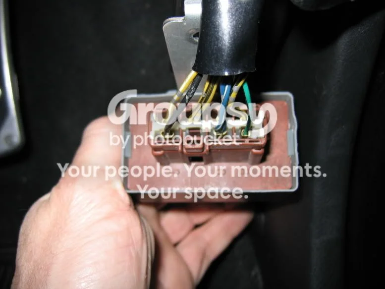
Tap right for next · left for back · Keys: ← → step · Space / PgUp / PgDn scroll · Esc exit