Honda Fit (GE8) Cup Holder LED Accent Lighting Install
Introduction
This guide covers adding LED accent lighting to the panel above the center-console cup holders on the second-generation Honda Fit (GE8, roughly 2009-2013), an area Honda left unlit from the factory. The finished mod softly illuminates the console and cup-holder area at night so you are no longer feeling around in the dark, and it switches on with the parking and headlights. Two approaches are described: a low-cost do-it-yourself version using a pair of small LEDs mounted in the existing panel, and an OEM-style retrofit that installs the later 2012 center cover already tooled for a factory bulb holder. Both draw power from the same switched lighting circuit, and the wiring can be arranged either to stay at full brightness with the lights on or to dim together with the dash illumination. The job suits a beginner comfortable with basic soldering and wire-tapping. Adapted from a community writeup by chubbykai on FitFreak (https://www.fitfreak.net/forums/2nd-generation-ge8-specific-diy-repair-maintenance-sub-forum/47740-diy-install-cup-holder-led-s-ge8.html), including corrections from the follow-up discussion.
Reference
Tools Required
- Stiff hooked trim tool or a bent length of firm wire for prying the panel
- Power drill with a 3 mm bit
- Wire strippers
- Soldering iron and solder
- Multimeter for identifying the correct circuit
- Zip ties
Parts Required
-
Two 3 mm LEDs (color of your choice)
-
Two 3 mm LED holders
-
Several feet of 18-22 gauge wire
-
1/4 inch wire loom
-
One wire tap (or a Bussmann ATM Add-A-Fuse as an alternative feed)
-
One inline connector so the panel can be unplugged later
-
Heat shrink or insulating tape
-
Optional OEM factory-look route: 2012 center cover 77290-TF0-G01ZA
-
Optional OEM route: bulb socket 35505-SA5-003 and a #74 / T-1 3/4 LED bulb
-
Optional: 2012-2013 cup holder 83403-TK6-A11ZA
Safety Warnings
- ⚠ Route and secure all wiring clear of the steering column and the brake and accelerator pedals so it can never interfere with vehicle controls.
- ⚠ Verify any wire with a multimeter before tapping it; confirm it is the intended switched circuit and not an unrelated live feed.
- ⚠ Observe LED polarity; an LED connected backwards simply will not light.
Step-by-Step Instructions
1 Remove the trim panel above the cup holders
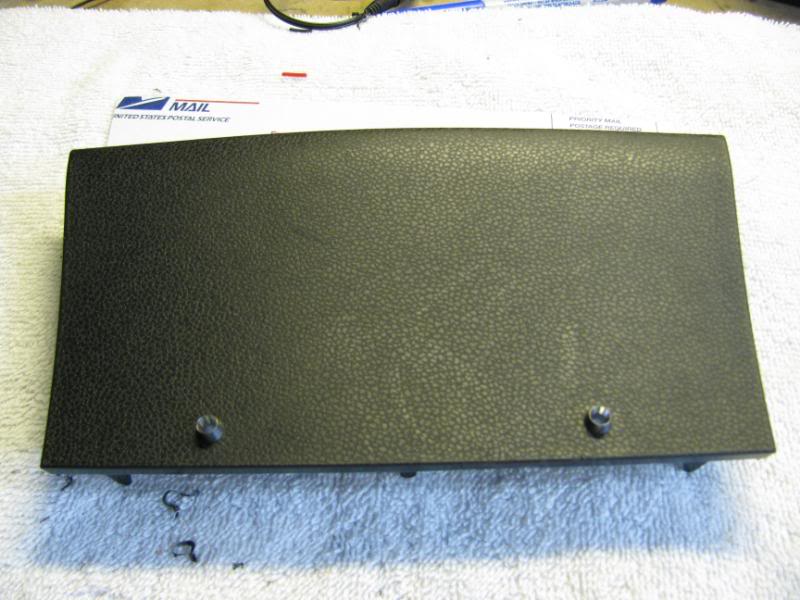
The trim panel directly above the cup holders is a tight press fit and resists coming out. Slip a stiff hooked trim tool or a bent length of firm wire behind its lower edge and pull outward with steady, even force to release the retaining clips. Work along the panel until it pops free, then set it face-down on a soft surface to protect the finish.
2 Plan the LED placement and drill the holes
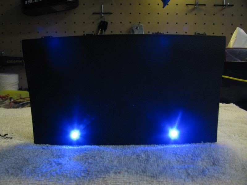
Decide where the two 3 mm LEDs will sit on the panel. Positioning them low on the face keeps the emitters and holders out of your line of sight while driving, so the cabin receives soft reflected light rather than direct glare. To confirm the layout before committing, trace the panel onto cardboard, transfer your measurements, and drill that mockup first. Once you are happy with the spacing, drill matching 3 mm holes in the panel and seat the LED holders.
3 Wire the two LEDs in parallel
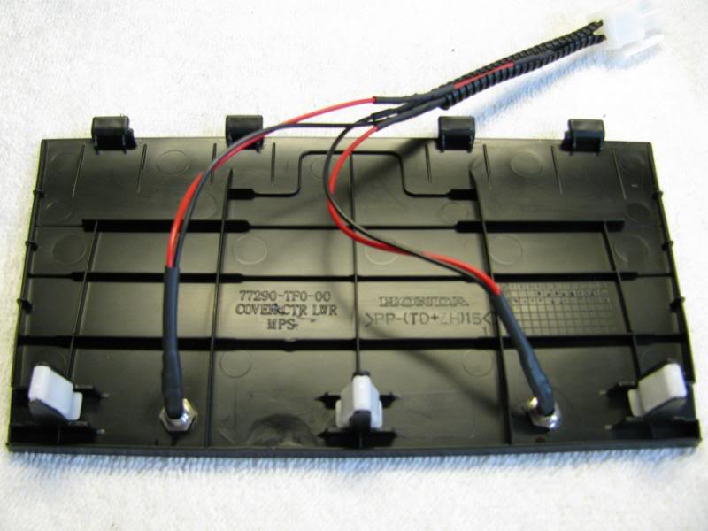
Join the two LEDs in parallel: connect both positive legs to a single power lead and both negative legs to a single ground lead, observing LED polarity throughout. Solder and insulate the joints. Fit an inline connector between the panel harness and the vehicle-side wiring so the panel can be unplugged and removed later without cutting the tap at the fuse box. Use 18-22 gauge wire and sleeve the run inside 1/4 inch loom for a clean finish.
4 Route the wiring down to the fuse panel
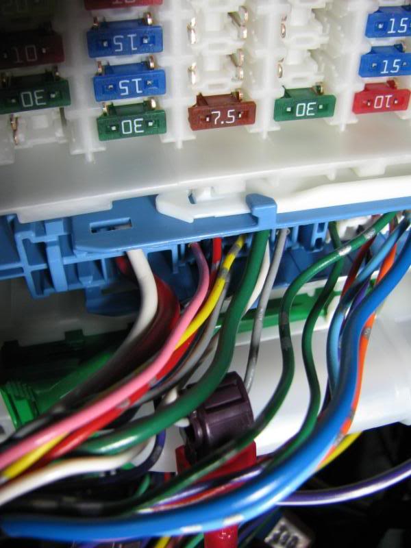
Feed the loomed wire from behind the panel down toward the fuse panel on the driver's side. Secure it with zip ties along a path of your choosing, keeping it well clear of the steering column and the brake and accelerator pedals so nothing can ever snag a moving control.
5 Tap a switched power source

At the fuse panel you will see three large multi-pin connectors, ordered top to bottom as blue, then green, then white. For lighting that comes on with the parking and headlights, tap the gray wire in the blue (top) connector, roughly the seventh position from the left on the upper row, which carries switched power from the light switch. Confirm the wire with a multimeter before committing, then attach the positive lead there with a wire tap. As a tidier alternative, an add-a-fuse such as a Bussmann ATM Add-A-Fuse fitted to the parking or headlight fuse gives a fused feed and pairs well with a small terminal block if you intend to power several LEDs from one point.
6 Ground the circuit, or wire it to dim with the dash
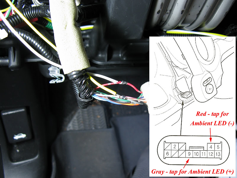
Attach the negative lead to a solid chassis ground point near the install. Wired to the plain light-switch feed, the LEDs glow at full brightness whenever the lights are on. To make them dim together with the dash instead, tap the dash illumination (dimmer) wire in place of the raw parking-light wire. The red dimmer ground wire can also be picked up on the A/C harness, which is easier to reach than routing all the way to the mirror controller.
7 Reinstall the panel and test
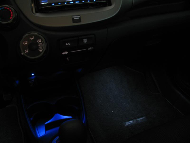
Reconnect the inline plug, tuck away any slack, and press the panel back into place until the clips seat fully. Switch on the parking or headlights and confirm both LEDs illuminate. If you wired the dimmer circuit, verify they brighten and dim as you turn the dash rheostat.
8 Optional: retrofit the OEM 2012 panel for a factory look
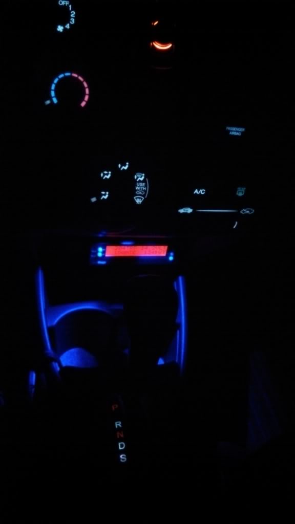
If you would rather not drill, retrofit the later 2012 center cover (part 77290-TF0-G01ZA), which already comes with the LED cutouts and an integrated bulb-holder mount. Press the OEM bulb socket (35505-SA5-003) into the cover with a #74 / T-1 3/4 LED bulb, then feed it from the same switched circuit used above. The cover installs in place of the original 2009-2011 panel and gives a clean factory appearance; fitting the 2012 cup holder (83403-TK6-A11ZA) at the same time also frees up room for taller cups.
Pro Tips
- 💡 Make a cardboard mockup of the panel and test-drill it first to lock in an LED placement you like before touching the real panel.
- 💡 Drill the holes near the bottom of the panel so the emitters are not visible while driving; the result is soft reflected light rather than direct glare.
- 💡 To dim the LEDs with the dash lights, tap the dash illumination wire rather than the plain parking-light feed. The red dimmer ground is also available on the A/C harness, closer than the mirror controller.
- 💡 A white LED around 3 lumen can be too bright and lights the center unevenly; a 1 to 1.5 lumen LED, a blue LED, or a diffusing tint over the hole tones it down.
- 💡 An add-a-fuse on the parking or headlight fuse feeding a small terminal block is a clean way to power multiple LEDs from a single source.
- 💡 The factory 2012 cover (77290-TF0-G01ZA) already includes the light holes and bulb mount for a near plug-and-play result.
Was this guide helpful?