Honda Fit (GD): Independent Fog Light Control Using the Factory Switch
Introduction
The factory wiring on the second-generation Honda Fit (GD) only allows the fog lamps to switch on once the headlights are already lit. This modification reroutes the fog trigger circuit through a fused tap in the interior fuse panel so the existing dash switch can turn the fog lights on by themselves, independently of the headlights. It is a low-cost, reversible interior electrical job that requires no drilling and no new switch. Note that this procedure keeps the fogs tied to the factory logic, so they will still cut out when the high beams are engaged and will dim with the dash at night; wiring them to stay on with high beams is a separate relay job not covered here. Adapted from a community writeup by SickFit on FitFreak (https://www.fitfreak.net/forums/fit-diy-repair-maintenance/26959-diy-independent-fog-w-original-switch.html), including corrections from the follow-up discussion.
Reference
Tools Required
- Wire cutters or cutting pliers
- Wire strippers
- Crimping tool (or a soldering iron and solder)
- Fuse puller (the white one stored inside the fuse panel)
- Vice grips or small pliers to seat the fuses
- Electrical tape
Parts Required
-
Roughly 2 feet of 14-16 gauge wire
-
ATM/Mini size add-a-circuit fuse tap rated to 10 amps
-
Two 10-amp ATM/Mini fuses
-
One crimp connector (or solder for the splice)
Safety Warnings
- ⚠ Install both 10-amp fuses in the add-a-circuit. Running only one fuse has repeatedly caused loss of power steering, gauges, speedometer and cruise control plus check-engine and airbag warning lights; revert immediately if this occurs.
- ⚠ Confirm you are cutting the red wire with the yellow stripe. Cutting the wrong wire has produced a check-engine light, an airbag warning light and disabled cruise control.
- ⚠ If a check-engine light appears after installing in slot 3, prefer slot 2 rather than removing the black Denso box beside slot 3.
- ⚠ Ensure every splice and cut end is fully insulated before reassembly to prevent shorts under the dash.
Step-by-Step Instructions
1 Remove the lower steering column trim cover
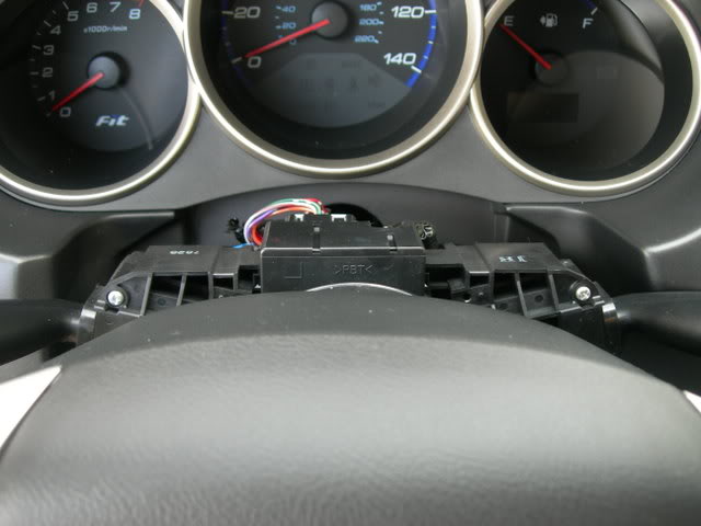
Pull the plastic shroud beneath the steering wheel away from the dash. It is retained by clips and releases with light hand pressure. Ease the clips out gently, because they are brittle and several people have snapped them during removal or when refitting the panel afterward.
2 Access the left-hand connector
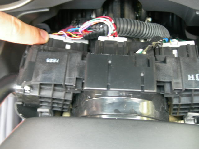
Behind the trim you will see three wiring connectors. Work with the one on the left. Unplug it from its socket so you can handle its wires freely on the bench of your lap rather than fighting them in place.
3 Identify and cut the fog trigger wire
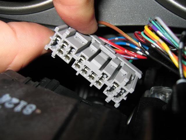
On that connector, locate the red wire carrying a yellow stripe. The original writeup labeled this 'yellow/red,' but a reader correctly flagged that it is actually red-dominant with a yellow tracer, and a later builder confirmed the same. Check it against the reference photos, then cut it about one to two inches out from the connector body.
4 Splice an extension lead onto the connector side
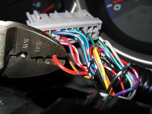
Keep the length of wire still joined to the connector; the short piece that fell loose is no longer needed. Strip roughly 1 cm of insulation to reach bare copper, then join about two feet of new wire to it, either by soldering or with a crimp connector. Choose a new wire close to the gauge of the factory lead so the joint is clean.
5 Insulate the leftover cut end
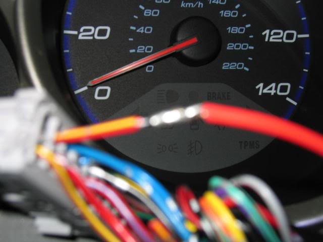
Wrap the short stub that remains in the loom with electrical tape so its exposed copper cannot contact anything, then tuck it out of the way.
6 Open the interior fuse panel
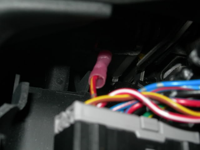
Find the fuse compartment door low on the left side of the steering column. Release its latch and take the cover off to expose the fuse layout inside.
7 Pull the fuse from slot 3
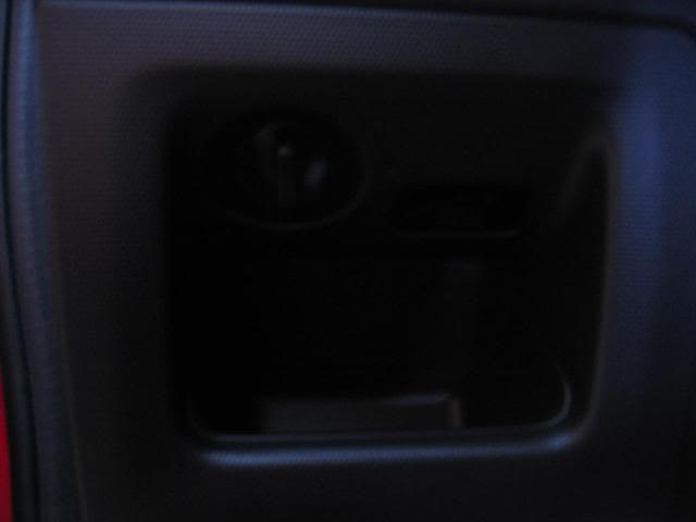
With the white fuse puller kept inside the panel, lift out the 10-amp fuse in position 3 and hold onto it, since it goes back into the tap in a later step.
8 Route the extension lead to the fuse panel
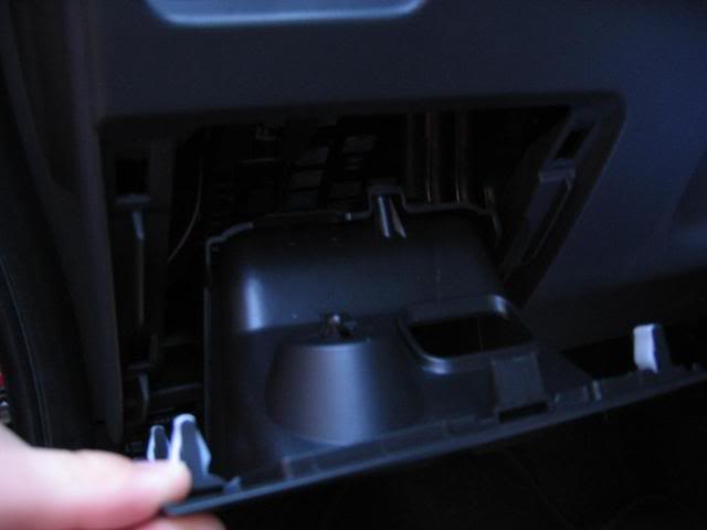
Feed the new wire from the steering column area down behind the trim toward the fuse panel. It should drop through the gap cleanly and reach the fuse compartment without forcing.
9 Crimp the wire to the add-a-circuit tap
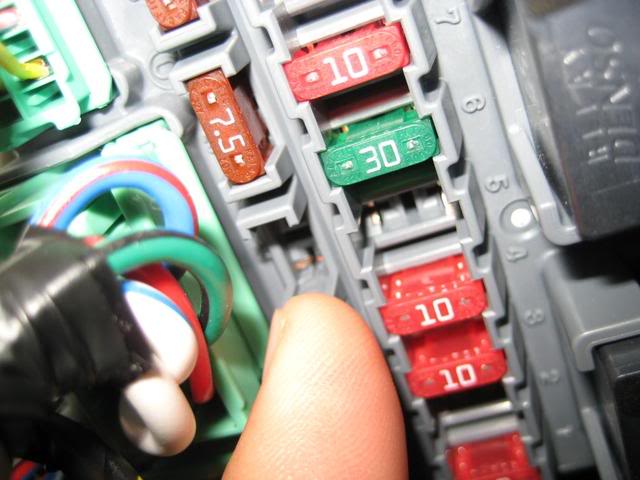
Trim the extension to remove excess slack, then crimp its end into the blue connector that ships with the add-a-circuit. Use an ATM/Mini-size tap rated to 10 amps; the larger ATO style is too big for this panel and will not seat, so confirm the package says ATM or Mini before you start.
10 Load both fuses into the tap
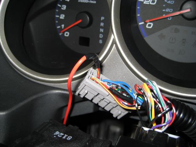
Seat a 10-amp fuse in each of the tap's two fuse positions. Both are mandatory: with only one fuse fitted, the shared circuit is broken and the car loses power steering, gauges, speedometer and cruise while warning lamps illuminate. The fuses are a very tight fit, so a careful squeeze with vice grips helps them seat fully.
11 Install the tap and reassemble
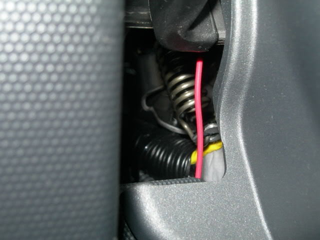
Push the loaded add-a-circuit into slot 3. Slot 2 is a good alternative: it sits on the ignition-switched supply and is easier to reach, which also avoids disturbing the black Denso box next to slot 3. Verify no bare copper is exposed anywhere, taping over any you find, then refit the fuse door and clip the steering column trim back on.
Pro Tips
- 💡 Slot 2 works as well as slot 3, sits on the ignition-switched supply, and is easier to reach; wiring to an ignition-switched slot means the fogs shut off when the key is out.
- 💡 Take the add-a-circuit out of its package and test-fit it in the panel before you begin, so you are sure it is the correct ATM/Mini size.
- 💡 The two fuses seat very tightly in the tap; a gentle squeeze with vice grips or pliers makes them go in.
- 💡 Some builders skipped the add-a-circuit entirely and used a U-shaped spade connector plugged into an empty ignition-switched slot with a single fuse.
- 💡 Disconnecting the battery is not required for this job.
- 💡 There is very little slack in the factory wiring and the area under the dash is cramped, so plan your routing before cutting the extension to length.
- 💡 The fogs will still dim along with the dash at night and will cut out when the high beams come on; keeping them lit with high beams needs a separate fog relay modification.
Was this guide helpful?