Honda Fit Footwell, Ambient, and Glovebox LED Lighting Installation
Introduction
This guide covers adding custom interior accent lighting to a second-generation Honda Fit (GE8 chassis, roughly 2009-2013; the same wiring logic adapts to the earlier GD chassis). You will build three independently triggered lighting zones: footwell courtesy lights that track the factory dome-light behaviour (fading in and out with keyfob lock/unlock and door open/close), ambient accent lights and glovebox lights driven by the parking/headlight switch, plus optional cup-holder and under-seat rear lighting. Rather than mounting a kit's supplied modules where they sit in plain view, the approach hides dimmed flux LEDs inside recessed trim so only the glow shows, and it swaps the kit's teal-tinted emitters for cleaner cool-white and blue LEDs. A repurposed dash switch, gated by a diode, lets the driver light just the footwells without waking the dome light. Total LED cost is modest (about $20-25 in LEDs plus the ambient kit). Expect to remove several interior panels and tap the under-dash fuse box, so plan for a patient afternoon of wiring. Adapted from a community writeup by Zalthras on FitFreak (https://www.fitfreak.net/forums/fit-interior-exterior-illumination/45011-diy-footwell-illumination-ambient-lights-glovebox-illumination.html), including corrections from the follow-up discussion.
Reference
Tools Required
- Interior trim/panel removal tools
- Soldering iron and solder
- Wire strippers and crimpers
- Heat-shrink tubing and heat source
- Small drill and bits (for LED lead holes)
- Digital multimeter or test light
- Insulated hand tools
Parts Required
-
Superflux (4-chip) flux LEDs for ambient accents
-
5.6kOhm current-limiting resistors (one per flux LED)
-
Cool-white LED modules: LBM-W2-LP (rear footwells, gloveboxes; also recommended for front footwells)
-
hf5-b5590 modules for the front footwell ambient (blue) accents
-
Ambient light kit (used for its harness and one center module), approx. $90
-
1N4001 50V diode (do NOT substitute a Zener)
-
Automotive primary wire, connectors, and heat-shrink
-
Optional: switched audio potentiometer for dimming the ambient circuit
-
Optional: 10mm chrome LED housings (fit the superflux 4-chip LEDs)
Safety Warnings
- ⚠ Disconnect the battery before probing or splicing at the under-dash fuse box; a slip near live MICU pins can short the circuit.
- ⚠ Verify every pin identity with a meter or test light before cutting in - do not assume a wire colour or position.
- ⚠ Use a standard rectifier diode (1N4001), never a Zener, in the footwell gating circuit, or the switch logic will not behave.
- ⚠ Solder and heat-shrink all connections and secure the harness; loose wiring behind the dash can rattle, chafe, or short over time.
Step-by-Step Instructions
1 Plan the three circuits and select LED modules
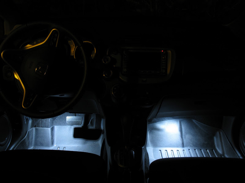
Decide the trigger for each zone before buying anything. Footwell courtesy lighting should follow the dome-light circuit so it fades with the doors and the keyfob; ambient and glovebox lighting should follow the parking/headlight switch so they glow whenever the running lights are on. For emitters, the original build used cool-white LBM-W2-LP modules in the rear footwells and gloveboxes, LBM-xW4 up front, and hf5-b5590 modules for the blue front ambient accents, all sourced from superbrightleds.com; oznium.com straight-black modules are an alternative. Apply the reporter's own correction here: the LBM-xW4 proved too bright and bulky for the front footwells, so use LBM-W2-LP there as well and reserve the xW4 for trunk lighting.
2 Build the hidden ambient assemblies with current-limiting resistors

The kit's supplied modules end up too visible on the passenger side and buried too deep on the driver side, and their colour reads as dark teal rather than a clean blue. Instead, fabricate concealed emitters: pair each superflux (4-chip) LED with a 5.6kOhm resistor to dim it, then seat it inside the recessed pocket of the footwell trim so the emitter itself is out of sight and aimed for an even wash of light. Drill a small set of lead holes through the trim to pass the LED legs. If you prefer a tidy pre-built part, oznium.com sells 10mm chrome housings that accept the superflux 4-chip LEDs and can ship them with the resistor already fitted and heat-shrunk.
3 Tap the dome-light feed for the footwell courtesy lights

At the under-dash fuse box, locate the dome-light connector that originates from the MICU. Pins G5 and G7 carry the pink +12V and the blue ground for that circuit. Splice the footwell LED feed into these two pins so the footwell lamps mirror the factory dome light exactly: they fade up when a door opens or the car is unlocked with the keyfob, and they fade back down on lock or door close. Confirm each pin with a meter before you cut into anything, since a wrong tap here can short a live circuit.
4 Mount the front and rear footwell modules

Fit the front footwell modules up under the dash trim, angled down toward the floor. For the rear seats, route the leads rearward under each front seat and fasten a module to the underside of the seat frame so it casts light onto the rear floor area. Keep the wiring runs tight against existing harnesses and secure them so nothing dangles into the pedal box or foot space.
5 Wire the glovebox lights to the parking-light circuit
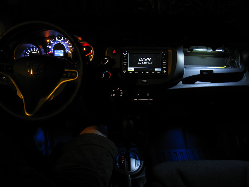
Install a module in each glovebox, upper and lower, and tie them to the parking-light circuit so both compartments illuminate whenever the running lights are switched on. Feed the leads through the glovebox housing where they stay clear of the hinge travel and the drop-down motion, and test that each box lights the moment it opens.
6 Add a center cup-holder light in the lower dash cover
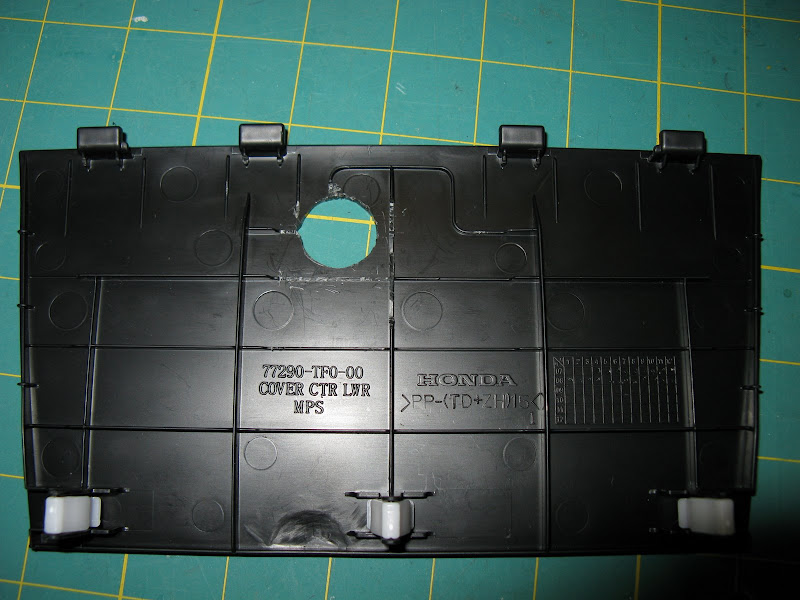
Repurpose one leftover module from the ambient kit as a light for the lower center console/cup-holder area. Drill an off-center hole in the rear face of the lower center dash cover so the module seats flush and points down into the cup-holder pocket, then wire it alongside the ambient/parking-light feed. Deburr the drilled hole so the module clips in cleanly.
7 Gate the repurposed dash switch with a diode

Free up the factory accessory switch for a second job. First cut and bypass its connector so the ambient and glovebox circuits stay powered directly from the parking lights. Then rewire the physical switch to the footwell lamps through a 1N4001 50V diode. Important correction: an early photo shows a 1N4748A Zener that was grabbed from a parts bin by mistake, and a Zener's reverse-breakdown behaviour is wrong for this job, so fit an ordinary rectifier diode. The diode passes current in a single direction, feeding the footwell LEDs from the door-open dome source while blocking the dash switch from back-feeding and waking the dome light (with the dome selector set to 'door'). The switch then becomes an on-demand control for the footwells alone.
8 Verify behaviour and reassemble
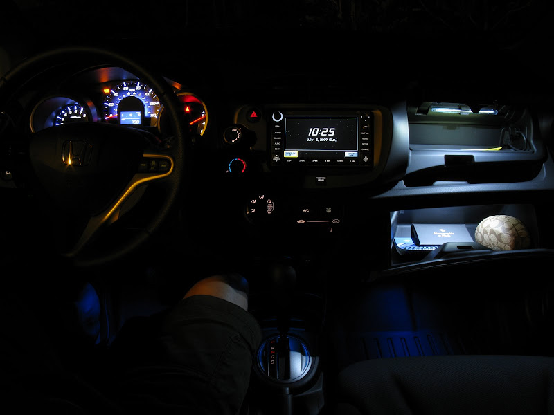
Reconnect power and walk through each state before closing panels. With the dash switch off, the footwells and dome light should come on together only when a door is open. With the dash switch on, the footwells should light while the dome light stays off. Cycle the parking lights to confirm the ambient, glovebox, and cup-holder lamps respond, and lock/unlock with the keyfob to confirm the footwells fade. Once every state checks out, heat-shrink and dress all splices, then refit the trim.
Pro Tips
- 💡 To dim or fully switch off the ambient circuit later, splice a switched audio potentiometer into its feed.
- 💡 Simpler alternative trigger: tap the gray parking-light wire so the footwells follow the headlights. They will blink briefly on lock/unlock, which can be worked around if it bothers you.
- 💡 The blue front ambient accents were the one part the original builder later regretted; consider skipping them and running all cool-white if you want a cleaner look.
- 💡 Ordering the flux LEDs from oznium with the resistor pre-installed and heat-shrunk saves fiddly bench work.
- 💡 Budget roughly $20-25 for the LEDs plus about $90 for the ambient light kit; wire and small hardware vary by what you already own.
- 💡 There is no Honda part number for a plug-and-play pigtail to the factory lighting switch (confirmed with a dealer parts desk); the raw connector is Sumitomo 6098-2779, and reusing the OEM switch without soldering otherwise means buying the whole kit.
- 💡 The OEM ambient-light switch itself is Honda part 08E10-TA0-1M035 if you are replacing a burned-out illumination bulb in it.
Was this guide helpful?