Honda Fit L15A7 Valve Clearance Check and Adjustment (2nd-Gen GE8)
Introduction
This guide covers checking and, where needed, adjusting the valve clearances (valve lash) on the Honda L15A7 1.5-liter four-cylinder used in the second-generation Fit (GE8, roughly 2009-2013, sold as the Jazz in some markets). The L15A7 runs a solid-lifter, screw-and-locknut valvetrain with no hydraulic self-adjustment, so the lash slowly drifts over tens of thousands of miles and must be measured and reset by hand. Honda treats this as a periodic service; owners who let it go commonly find the exhaust valves have tightened below specification, which shows up as a rough idle, dulled throttle response, and, over the long term, accelerated valve and ignition-coil wear. The measurement must be taken with a fully cold engine, and reaching the cam area on this car requires stripping off a fair amount of intake and cowl hardware. Budget two to three hours the first time. Note that a valve adjustment on its own does not always resolve an idle stutter or misfire - several owners here ultimately traced those symptoms to spark plugs or ignition coils - so treat this as one part of a broader tune-up rather than a guaranteed cure. Adapted from a community writeup by mhadden on FitFreak (https://www.fitfreak.net/forums/2nd-generation-ge8-specific-diy-repair-maintenance-sub-forum/75306-diy-valve-clearance-check.html), including corrections from the follow-up discussion.
Reference
Tools Required
- Metric feeler gauge set (bent-tip / offset blades strongly recommended)
- 10mm open-end wrench
- Small flathead screwdriver
- Phillips screwdriver
- 3/8-inch and 1/2-inch ratchets with extensions
- Deep/extended 10mm, 12mm, and 19mm sockets
- Needle-nose and flat-jaw pliers
- Jam-nut valve adjustment tool (e.g. Alltrade 648827 10mm) - optional but helpful
- Torque wrench (for spark plugs, if servicing them)
Parts Required
-
Hondabond or equivalent gasket sealant
-
Valve cover gasket, Honda 12341-RB0-003 (optional - only if the original is damaged or you choose to replace it)
-
Spark plugs (optional - convenient to replace while the cover is off)
Safety Warnings
- ⚠ Measure only on a fully cold engine that has not run for at least 6-8 hours - warm clearances read incorrectly.
- ⚠ Turn the crank clockwise only; never rotate it backward.
- ⚠ Disconnect and remove the battery before working around the engine.
- ⚠ Valve cover bolts strip and snap easily - do not over-torque them, and stop if one feels seized.
- ⚠ The vehicle is undrivable during this procedure; have alternate transport and all tools ready before you start.
Step-by-Step Instructions
1 Prepare the Vehicle and Set Up Crank Access
Work only on a fully cold engine: leave the car unrun for six to eight hours so everything sits at ambient temperature, because warm components read out of spec. Park on level ground and make sure a second vehicle is available, since the Fit will be undrivable through the whole job. Before removing anything, steer the front wheels fully to the right by hand with the engine off. This lines up an access opening in the wheel well on the passenger side, giving you later access to the crank pulley bolt so the engine can be turned over without pulling the road wheel.
2 Remove the Air Filter Box and Battery

Open the hood. Release the retaining clips and the MAF sensor connector, then lift out the air filter housing and its element. With a 10mm socket, disconnect the battery terminals and the hold-down bracket - the bracket's hooks slide out from beneath the battery base, so it need not be fully unbolted. Lift out the battery, then remove the battery tray and bracket to open up working room above the engine.
3 Detach the Airbox from the Throttle Body
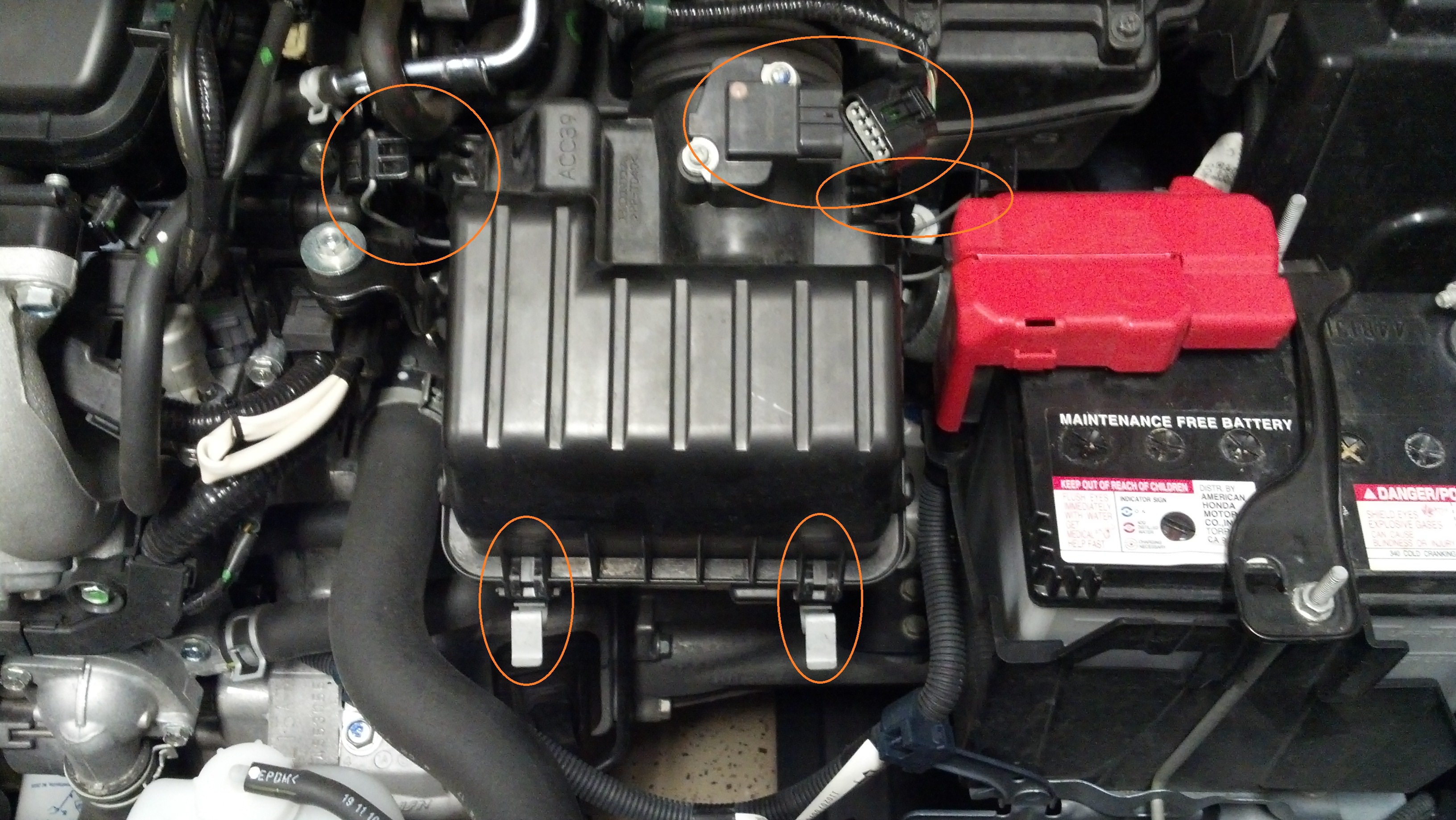
Loosen - but do not fully unscrew - the clamp holding the remaining intake tube to the throttle body; a molded stop prevents the tube from sliding rearward. Remove the two 10mm bolts that secure the airbox bracket to the block and gearbox, then release the green wire clip. Ease the assembly off the throttle body. Use pliers to work the metal vacuum tube off its rubber grommet, relieving pressure rather than yanking it, then set the airbox aside.
4 Remove the Throttle Body

Undo the four 12mm bolts securing the throttle body, taking care to keep the metal brackets on its front and rear faces. Disconnect the two electrical connectors. Swing the throttle body clear of the intake path; you can leave its lines attached and simply support it out of the way.
5 Remove the Intake Manifold

Take out the five 12mm bolts joining the plastic intake plenum to the metal manifold and remove the metal bracket behind it. Remove the two 10mm bolts located behind the plenum, then the final 12mm bolt on its side. Detach the vacuum line at the valve cover and unclip the hose running to the back of the plenum from its bracket - that hose can stay attached to the plenum while you lay the assembly aside.
6 Remove the Cowl and Wiper Assembly (2nd-Gen Fit)
On the second-generation Fit the valve cover tucks under the windshield cowl, and clearance is too tight to measure and adjust accurately with the cowl in place. Remove the wiper arms, the wiper motor and linkage, and the plastic cowl panel - it is a designed service-removable part and comes off in a few minutes once the wipers are clear. Keep spare cowl clips on hand, as the originals can break. Working with the cowl still fitted is possible but makes the rear valves considerably harder to reach.
7 Disconnect the Coils and Remove the Valve Cover

Unplug each ignition coil connector, release the wiring bracket on the left side, and move the harness out of the way. Remove the eight 10mm bolts around the perimeter of the valve cover and lift it off. Go gently - more than one owner has snapped a valve cover bolt here, so if one feels seized, stop and free it rather than forcing it. Set the cover and its gasket somewhere clean for inspection and resealing later.
8 Rotate Each Cylinder to TDC

Fit the 19mm socket on an extension through the wheel-well access hole and turn the crank clockwise only - never in reverse. Watch the cam gear: a cylinder is ready to measure when its number sits at the twelve-o'clock position and the scribe line on the cam gear hub is level and flush with the top edge of the cylinder head. Bring each cylinder to top dead center in the firing sequence 1-3-4-2, rotating the crank between cylinders. At TDC for a given cylinder, both its intake and exhaust valves are closed and can be measured.
9 Measure the Valve Clearances

With the cylinder at TDC, slide the correct feeler gauge between each cam lobe and its follower. A correct clearance gives light drag and a faint vibration as you draw the blade back and forth - neither free-sliding nor pinched. Do not flex the blade, which falsifies the reading; bent-tip (offset) gauges make the tight spaces far easier. Cold specification is Intake 0.15-0.19 mm (0.006-0.007 in) and Exhaust 0.26-0.30 mm (0.010-0.012 in). In practice the exhaust valves are the ones most often found tight. Record every valve before touching an adjuster.
10 Adjust the Out-of-Spec Valves

For any valve outside spec, loosen the locknut with a 10mm open-end wrench and turn the adjuster screw with a flathead screwdriver. Set the gap with the target feeler blade in place: snug the screw down until the blade can just barely no longer be pulled free under light force, keeping the blade moving so it does not bind. This part is critical - tightening the locknut lifts the adjuster and opens the gap slightly, so hold the screw dead still with the screwdriver while you torque the locknut, then re-measure. A jam-nut valve adjustment tool (for example the Alltrade 648827 10mm) makes holding the screw while locking the nut much easier. Many owners aim for the loose end of the exhaust range and use a go/no-go check - one thousandth over the target is no-go, one under is go.
11 Reseal the Valve Cover and Reassemble

Once every cylinder is verified, reassemble in reverse order. Scrape and clean the valve cover and head sealing surfaces so the gasket seats cleanly; reuse the gasket if it is intact, or fit a new one (Honda 12341-RB0-003). Apply a dab of Hondabond or equivalent sealant to the cam-cap seams at the front and rear of the head before lowering the cover. Reinstall the eight cover bolts snugly without over-tightening, then refit the coils, intake manifold, throttle body, airbox, battery, and cowl. If you pulled the spark plugs while in here, torque them to 20 lb-ft. A slightly louder tick afterward is normal for this solid-lifter engine, especially with the exhausts set toward the loose end of spec.
Pro Tips
- 💡 Exhaust valves are the ones most commonly found tight on this engine; owners report needing checks anywhere from 28k-50k miles onward, with roughly 60k-80k as a typical service interval.
- 💡 Bent-tip (offset) feeler gauges make the cramped cam area much easier to measure accurately than straight blades.
- 💡 Use a go/no-go approach: for a 0.012 in target, treat 0.013 in as no-go and 0.011 in as go.
- 💡 A valve adjustment alone may not cure an idle stutter or misfire - if symptoms persist, suspect the ignition coils or spark plugs.
- 💡 Since so much intake hardware comes off, this is a good time to also replace spark plugs and do an oil change or other scheduled service.
- 💡 Some engine tick is inherent to this solid-lifter design and is not a sign of a bad adjustment.
Was this guide helpful?