Honda Fit (GD) HVAC Control Panel LED Illumination Conversion
Introduction
This guide converts the factory incandescent lighting in the climate-control panel of the first-generation Honda Fit (GD, L15A) to LEDs, letting you match the HVAC glow to the rest of your interior in any color you like. Four #74 wedge bulbs behind the temperature, fan, and mode controls are swapped for LED equivalents, the passenger-airbag and A/C-defrost switch icons are re-tinted to suit, and an optional pair of pre-wired LEDs can be added to throw usable light down into the cupholders, which the factory leaves almost dark. The job requires pulling the center trim, unbolting the radio, and extracting the whole HVAC assembly to a bench, so it is more involved than a simple bulb change. Because the LEDs are polarized and slightly larger than the originals, each is press-fit into its retained base and confirmed for correct orientation before final assembly. Adapted from a community writeup by billmus86 on FitFreak (https://www.fitfreak.net/forums/fit-interior-exterior-illumination/21220-led-hvac-diy-w-pics.html), including corrections from the follow-up discussion.
Reference
Tools Required
- Long-reach Phillips screwdriver
- Short/medium Phillips screwdriver
- Wire strippers
- Hot glue gun with glue sticks
- Sharpie marker matching your chosen LED color
- Electrical tape
- Socket wrench with a long extension (backup for the hex-head radio screws if they strip)
Parts Required
-
4x #74 wedge-base LED bulbs in your chosen color (red, amber, green, blue, white, or UV; approx. $1.19 each)
-
Optional: 2x pre-wired LEDs on leads (inline resistor, ready for 12V) for cupholder down-lighting
-
Short lengths of red and black hookup wire (offcuts from the pre-wired LED leads work)
Safety Warnings
- ⚠ Retrieve the radio anti-theft security code before disconnecting power, or the head unit will lock out.
- ⚠ The passenger airbag (SRS) wiring runs through this assembly; handle its harness and connector carefully.
- ⚠ The blue, orange, and purple control cables are fragile; do not bend or kink the linkage wires during removal or reinstallation.
- ⚠ Do not drop the upper radio screws into the assembly; a screw lodged in the HVAC gears will jam knob movement.
Step-by-Step Instructions
1 Record the radio code and select bulbs
Before disturbing any wiring, locate and write down the radio anti-theft security code so you can reactivate the head unit afterward. Order four #74 wedge-base LEDs in the color you want; the color choice is purely cosmetic, so pick whatever matches your gauges and interior accents. Avoid the high-power #74 versions, which are uncomfortably bright for panel backlighting. If you also want the optional cupholder down-lights, add two of the pre-wired LEDs on flying leads; these already have an inline resistor and are ready for 12V, so no extra components are needed.
2 Remove the glove box
With the glove box shut, take out the two screws along its lower edge using a standard-length Phillips driver. Open the box and squeeze both side walls inward to clear the rubber stops, then lift the entire glove box away. This exposes the back of the HVAC housing and the three control cables running to it.
3 Release the three control cables
Three plastic-sheathed cables drive the climate controls: blue for the temperature linkage, orange for the vent/mode selector, and purple for fresh-air/recirculate. Each cable end is a loop held on a plastic peg by a small triangular tab. Press the tab in with one finger and slide the loop off the peg with the other. Unclip the orange and purple sheaths from their retaining clamps. For the blue cable it is easier to remove the single screw holding its mounting plate than to fight the clamp.
4 Remove the lower center trim panel
With a smaller Phillips driver, take out the single screw beneath the fan-speed knob, just above the cupholders. Free the lower trim panel by popping it downward and out; the easiest approach is to reach in through the open glove-box aperture where the linkage passes through and push the panel off from behind rather than prying at the visible face.
5 Unbolt the radio and HVAC assembly
With the lower trim off, look up into the underside of the radio to find two screws, one on each side, seated well up inside. Use the long-reach Phillips driver to remove them. These heads are hex-shaped, so if one begins to strip, switch to a socket on a long extension. Then unplug the two connectors under the HVAC unit: one feeds the fan-speed control, the other supplies the lighting and the relay that switches on the A/C when the mode knob is turned.
6 Free the panel from its clips and disconnect the harnesses
The center panel is held by numerous spring clips. Work steadily around the perimeter, starting at the bottom, and ease it out; losing one or two clips is not a problem given how many there are. Pull only far enough to reach the remaining connectors, since the harnesses are short. Disconnect the three radio connectors, the passenger-airbag indicator connector, and the A/C-defrost switch connector. The airbag wiring is loomed and clipped to the frame; pinch the base of that clip and lift the loom to release it.
7 Extract the assembly and move to a bench
Ease the complete assembly out of the dash, guiding the control linkage so it does not snag on anything as it comes through. Take the unit to a clean, well-lit bench where you can work on it comfortably.
8 Separate the switch modules and knobs
Remove the eight Phillips screws securing the white HVAC control block. Slide the passenger-airbag module and the A/C-defrost switch module out toward the front, each released by pressing its retaining clip; two of the screws face each other behind the airbag module. Two further screws sit by the fresh-air/recirculate switch, one hidden until you slide that switch aside. The control knobs are the last thing holding the white block to the black housing, so separate the white block from its black housing by hand and let the knobs spring off, keeping track of where they land.
9 Remove the diffusers and stock bulbs
Inside you will find the four backlight bulbs, likely wearing blue gel sleeves, plus two clear plastic diffusers held by a screw each that carry light up to the recirc/fresh-air switch. Remove those two screws and lift out the clear pieces. Leave the black twist-lock bulb bases in place and simply pull the incandescent bulbs out of them.
10 Fit and polarity-test the LEDs
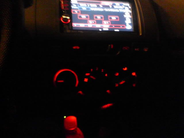
The LEDs are slightly fatter than the stock bulbs and will not seat if you try to reinstall them in the twist-lock base, so leave each base in its housing and press the LED directly into it. Because the LEDs are polarized, seat them loosely first, then reconnect the small lighting connector at the car and switch on the parking lights to check each one. If a bulb stays dark, rotate it 180 degrees. Once orientation is confirmed, draw a matching alignment mark across each LED and its housing with a Sharpie so you can restore the correct polarity if a bulb ever backs out.
11 Secure the LEDs
Begin with the two center bulbs. Hold each LED fully seated and drive its clear diffuser screw back in; the domed recess in the diffuser presses the LED deeper as the screw tightens, so run it down until it stops without overtightening. For the two outermost bulbs, which have no diffuser to trap them, press each home and apply a bead of hot glue between the LED and the surrounding white plastic, carrying a little glue over the top of the LED. Hold it until the glue sets and confirm it no longer moves, keeping the glue contained within the housing.
12 Re-tint the airbag and A/C-defrost switch icons
To make the passenger-airbag indicator and the A/C-defrost switch match your new color, pop off their outer switch caps and color the entire inside of each cap with the matching Sharpie, pressing the tip into every corner. Hold each cap to a light to confirm the whole icon is evenly covered. Whether you keep or remove the blue gel sleeves on these small bulbs depends on your target color: keep them for a blue look, remove them for a more orange output. Reassemble the switch caps but do not reinstall the modules into the panel yet.
13 Optional: add cupholder down-lights
Cut each pre-wired LED's leads down to roughly six inches. Join the two red leads to a single red offcut and the two black leads to a single black offcut. Splice this pair into one of the four existing backlight feed wires on the back of the white block, connecting the LEDs' black lead to the car's red wire and the LEDs' red lead to the car's green wire. Test at the car with the parking lights on before finalizing; if the pair stays dark, swap the connections (reversed polarity will not harm anything). Tape the splices, fit the supplied grommets into the two holes above the lenses from below with the flat side down, route the leads and push each LED out through its grommet, holding the grommet so it does not pop free.
14 Reassemble the dash

Refit the white control block into the black housing without pinching a wire, replace all eight screws, and press the knobs back on. Reinstall the airbag and A/C-defrost modules. Feed the control linkage back through to the glove-box opening carefully so the cables are not kinked. Reconnect the radio and remaining connectors, then press the center panel back onto its clips. The two upper screws that run up to the radio are awkward to start; refit them if you can, but the clips hold the panel securely if one will not seat. Reconnect the blue, orange, and purple cables to their correct pegs, check knob and switch travel before clipping the sheaths at the right tension, and rescrew the blue cable's mounting plate. Refit the lower trim panel and its screw, then reinstall the glove box and its two lower screws. Enter your radio code to finish.
Pro Tips
- 💡 Mark each LED and its housing with a matching Sharpie line so orientation and polarity can be restored if a bulb pops loose.
- 💡 Start with the two center bulbs, which are the most awkward to reach once the diffusers go back in.
- 💡 The blue gel sleeves shift the light toward white; remove them for a warmer, more orange output.
- 💡 A little rubbing alcohol on a cotton swab lifts the Sharpie tint cleanly if you later want to change colors.
- 💡 The pre-wired LEDs ship with about three feet of lead; keep the offcuts for splicing and to patch any wire you trim too short.
- 💡 Skip the high-power #74 LEDs; standard-brightness LEDs are already brighter than the factory bulbs.
Was this guide helpful?