Honda Fit (3rd Gen GK) Footwell LED Lighting Tied to the Dome Light Circuit
Introduction
This guide covers adding footwell lighting to a third-generation Honda Fit (GK) that switches on with the interior dome/courtesy circuit. The strips illuminate the front and rear floor areas when a door opens or the doors are unlocked by remote, then go out when the dome light does, so they are not always-on ambient lighting. Beyond the visual effect, the extra floor light makes it far easier to spot dropped items in the dark when entering or leaving the car. The build taps the factory dome-light signal at the driver's-side fuse panel, so no permanent cutting of vehicle harnesses is required and the install can be fully reversed. It suits owners comfortable with basic soldering and careful low-voltage wiring. This guide also folds in the follow-up discussion, most importantly the correction that the inline fuse belongs on the positive lead of a negative-ground vehicle, and the more secure fuse-tap connection method. Adapted from a community writeup by tbFit on FitFreak (https://www.fitfreak.net/forums/3rd-gen-gk-specific-fit-interior-modifications-sub-forum/87882-diy-footwell-lighting-w-dome-not-ambient.html), including corrections from the follow-up discussion.
Reference
Tools Required
- Soldering iron and solder
- Heat-shrink tubing and a heat source
- Wire strippers and crimpers
- Pliers (for shaping the connector)
- Trim/panel removal tool and a screwdriver
- Test light or multimeter
- Zip ties
- Drill with a small bit (optional, for anchoring)
Parts Required
-
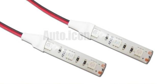
2x 3-SMD LED strip lights (4 individual lights total); blue or red as preferred
-
Inline mini blade fuse holder with a 10A fuse
-
1/4" convoluted (split) loom tubing
-
Fuse-panel connection: slim spade terminal, RS232 female crimp pins, or a fuse tap
-
Hook-and-loop (Velcro) fastener strips
-
Extra primary wire for cross-cabin runs
Safety Warnings
- ⚠ On a negative-ground vehicle the inline fuse must be on the positive lead. Fusing only the negative leaves the positive wire able to short to the chassis unprotected.
- ⚠ Do not let an under-dash light strip hang free where it could fall over the pedals; anchor it with zip ties.
- ⚠ When slipping a connector onto a fuse-panel pin, ensure it does not touch adjacent pins.
Step-by-Step Instructions
1 Understand the dome-circuit tie-in
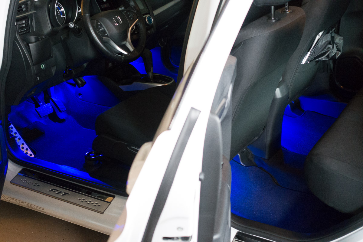
Plan to wire the strips to the interior dome (courtesy) circuit so they behave exactly like the dome light: on when a door opens or the car is unlocked, off shortly after. On the Fit, this signal is available at the fuse panel behind the driver's lower dash, on the eight-pin connector that the OEM door-sill garnish kit uses. The LED positive lead will go to the switched hot pin, and the LED negative lead to the return pin that completes the circuit when a door opens.
2 Access the fuse panel
Reach the fuse panel by removing the driver's-side lower trim, following the same teardown described in Honda's OEM under-dash illumination kit instructions. On the driver's side (the one with the cup holder), pry the side panel loose, then remove the single screw exposed at its base. With that free, release the panel beneath the steering column by pulling it down and outward, the same motion used to drop the panel under the glove box. This opens up working room at the fuse panel.
3 Identify the two dome pins
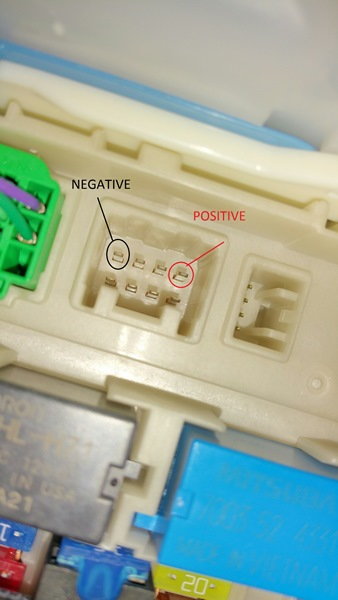
The eight-pin fuse-panel connector is arranged as pins 1-2-3-4 across the top and 5-6-7-8 across the bottom. Two pins carry the dome signal and switch with the doors: Pin 4 serves as the hot lead, while the return lead that completes the circuit is Pin 1. Confirm both with a test light or multimeter while opening and closing a door before committing any wiring.
4 Build the LED harness and add the fuse
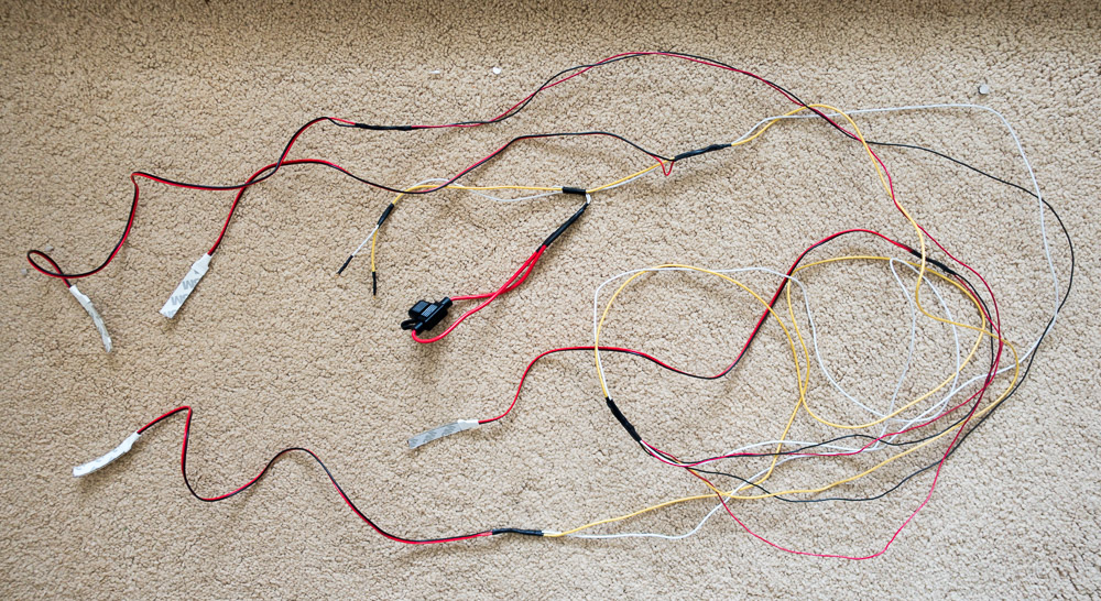
Combine the four strip leads into one positive bus and one negative bus. Solder every joint and seal each with heat-shrink for a durable, tidy harness. Install the inline mini blade fuse holder with its 10A fuse on the positive (hot) lead. This point was corrected in the discussion: on a negative-ground car the fuse must protect the positive conductor, not the negative, so that a positive wire touching the chassis cannot short unfused. Finally, sheath the bundle in 1/4" convoluted tubing so it resembles the factory looms.
5 Make the fuse-panel connection
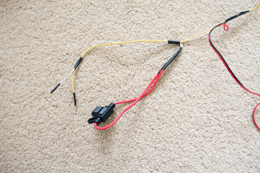
No off-the-shelf plug fits the small flat pins directly. Fabricate a slim terminal: take a small spade connector, cut it down to a single flat face, and squeeze it flatter with pliers until it slides onto one pin without bridging its neighbours. Two RS232 female serial-cable crimp pins pushed onto the terminals also work. For a more secure and easily reversible connection, use an inexpensive fuse tap on the hot side instead of forcing a bare pin.
6 Route the wiring
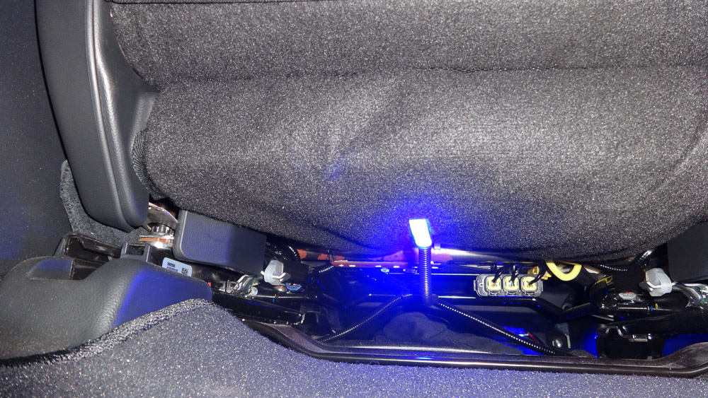
Run the sheathed harness from the fuse panel along the center console toward the seats, keeping it inside the convoluted tubing so it is protected and hidden. Where the run continues to under-seat lights, dress the cable alongside the existing seat wiring and secure it with zip ties. This keeps the wiring taut and prevents snagging as the seat slides fore and aft. If you extend a strip to the opposite side of the cabin, add primary wire before the connection point rather than at the light.
7 Mount the light strips
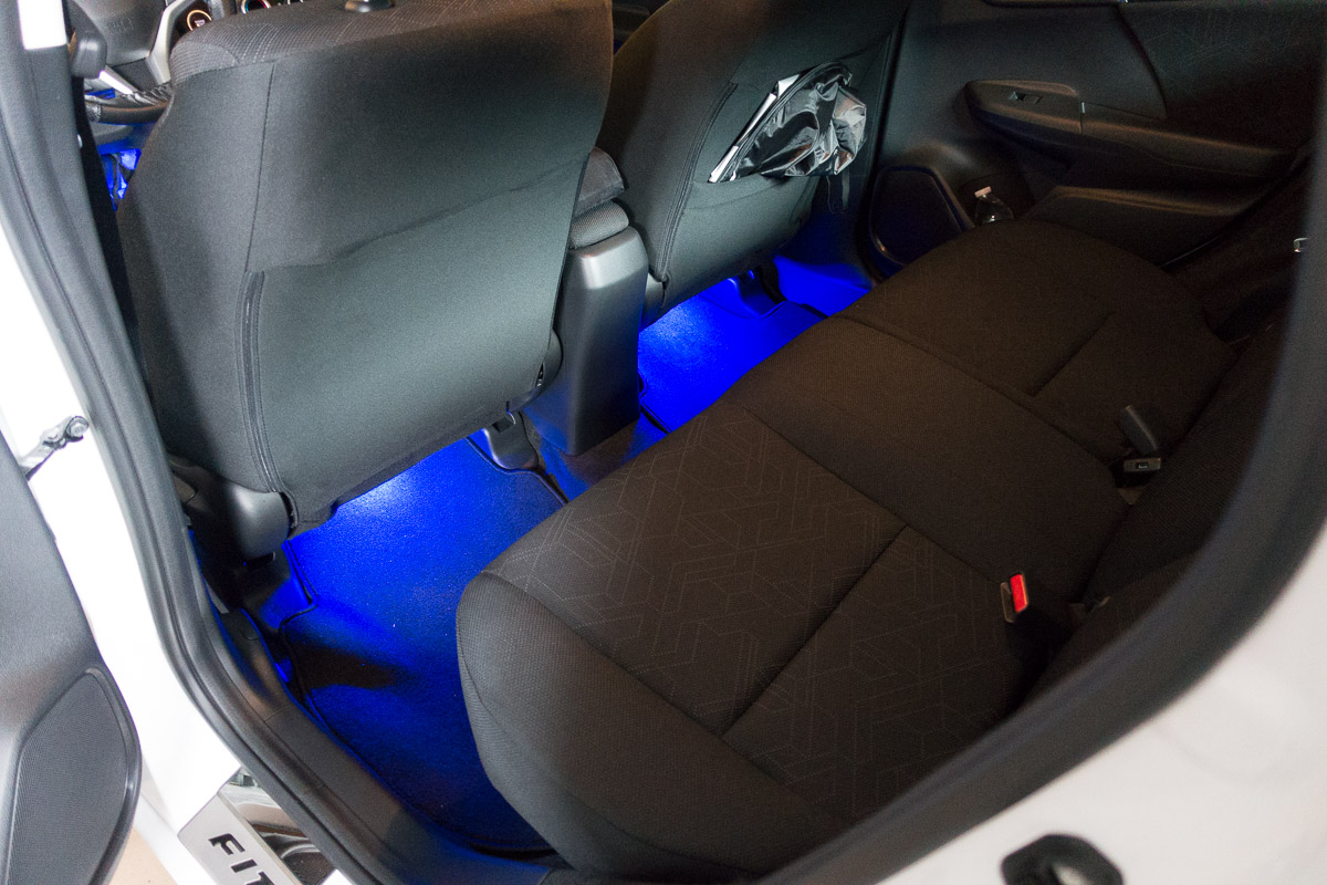
Front strips mount under the dash, aimed at the footwell. For the rear, use the underside fabric of the seat as one half of a hook-and-loop fastener: apply the mating hook/adhesive strip to the light where its factory 3M tape sits, then press the light up into the seat cloth so it grips. Warm the flexible strips before installation, since they stiffen in the cold and will not conform or adhere as well; positioning them near a heat vent first helps the tape bond.
8 Secure connections and test
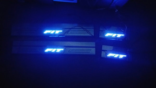
Open and close each door and cycle the dome switch to confirm the strips track the dome circuit and go out with it. If any terminal works loose over time, re-crimp it firmly; a properly tight crimp can stay seated for tens of thousands of miles. As a safety measure, prevent any under-dash strip from dropping toward the pedals by drilling a couple of small holes in the under-dash cover and anchoring the light with zip ties.
Pro Tips
- 💡 A camera exaggerates the intensity of blue strips; they appear noticeably brighter in photos than in person.
- 💡 You can add a SPDT switch to also run the footwell lights while driving, or to toggle them between manual-on and dome-triggered operation.
- 💡 A fuse tap makes a far more secure connection than a bare flattened pin, which can vibrate loose over time.
- 💡 Red LEDs give a look OEM kits cannot match at a fraction of the cost, and match well with warm-toned gauge lighting.
Was this guide helpful?