Acura RSX (DC5): Wiring an OEM Fog Light Switch to a Replica Fog Harness
Introduction
Aftermarket and eBay fog light kits for the Acura RSX (DC5, roughly 2002-2006) ship with a cheap replica switch that often refuses to hold an off state or lacks proper backlighting. Replacing it with the genuine Acura fog switch gives a factory look and reliable operation, but the OEM switch carries five terminals while a typical replica harness offers only four, so the two must be reconciled by hand. This guide covers identifying both pinouts, joining the switch to the harness function-by-function, handling the extra ground pin, and curing the common fault where the red backlight stays lit whenever the car is running. Basic soldering and an understanding of how a simple switched circuit works are all that is required. Adapted from a community writeup by KazeSpec on Club RSX (https://www.clubrsx.com/threads/diy-oem-fog-switch-to-replica-harness.469745/), including corrections from the follow-up discussion.
Reference
Tools Required
- Soldering iron or gun (crimp or spade connectors as an alternative)
- Electrical tape
- Wire strippers and cutters
- Multimeter / voltmeter for identifying pins
- Small needle-nose tweezers (for releasing wires from a cruise control connector)
Parts Required
-
OEM Acura fog light switch (about $15)
-
Replica or aftermarket fog light harness
-
16-18 gauge wire (five short leads)
-
Optional: OEM connector 04321-SR3-306 (5P 090 F) with pigtail pack 04320-SP0-B00 (red) or 04320-SP0-A00 (yellow) for a removable plug
Safety Warnings
- ⚠ Always disconnect the negative battery terminal before wiring to avoid blowing fuses or shorting the circuit.
- ⚠ Undersized wire can overheat: melted fuse holders and burnt relay wiring have been reported. Use adequately sized wire with the correct fuse and relay for the fog light load.
- ⚠ Insulate every exposed pin; the terminals sit close together and will short if left bare.
Step-by-Step Instructions
1 Disconnect the battery before starting
Remove the negative battery terminal so the circuit is completely dead before you touch any wiring. Working with power live invites shorts and blown fuses. Leave the battery disconnected until every joint is made and insulated.
2 Map the five terminals on the OEM switch
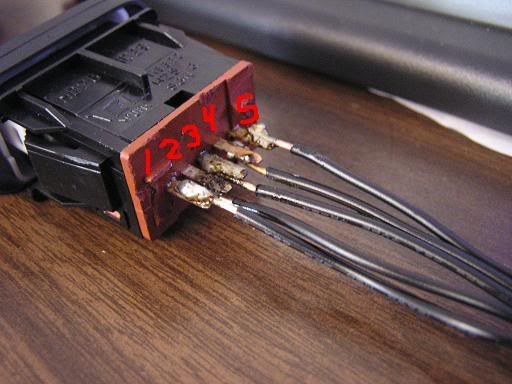
The genuine Acura switch uses five pins. Counting from the bottom of the switch upward, pin 1 supplies power to the on/off function, pin 2 is the positive that closes that on/off circuit, pin 3 feeds power to the illumination, pin 4 is the ground for the illumination, and pin 5 is the ground for the on/off function (pin 5 sits at the very top). Note that there are two separate grounds: one for the button action and one for the backlight.
3 Identify the four wires on the replica harness
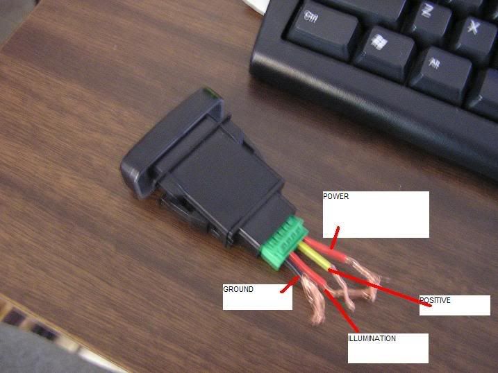
A typical replica or aftermarket harness terminates in four pins instead of five: pin 1 power, pin 2 positive to close the circuit, pin 3 illumination power, and pin 4 a single ground shared by both the switch and its light. Because the OEM switch expects two grounds and the harness provides only one, you will bridge that gap in a later step.
4 Cut away the brown guard over the OEM pins
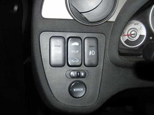
The OEM switch arrives with a brown plastic shroud shielding its terminals. Trim that cover off to expose the bare pins so wire can be attached. The brown housing is itself a sign that the switch is a genuine OEM part rather than a replica.
5 Attach leads to the five switch pins
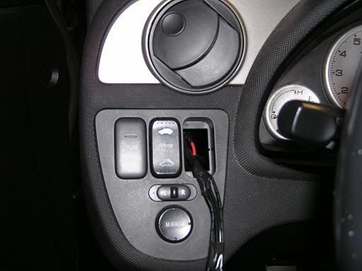
Run a short length of 16-18 gauge wire to each of the five terminals. Soldering makes the most dependable joint, though crimp or spade connectors are a fine substitute if you are not confident with an iron. Wrap each finished terminal in electrical tape, since the pins sit close together and will short against one another if left bare.
6 Match the switch wires to the harness by function

Join the four common functions straight across: switch pin 1 to harness pin 1, pin 2 to pin 2, pin 3 to pin 3, and pin 4 to pin 4. Keep power to power and illumination to illumination. Do not transpose the pin 1 and pin 3 leads even if they happen to share a wire color; crossing those two leaves the switch stuck permanently on, though it will not blow a fuse as long as the circuit is grounded.
7 Ground the fifth pin
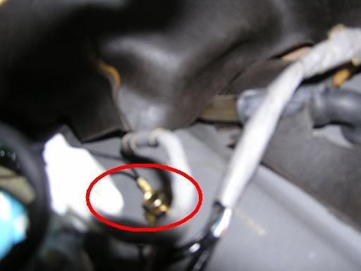
The switch's second ground (pin 5) has no matching wire on a four-pin harness. Two approaches work. You can run pin 5 to a chassis ground bolt under the dash, or you can simply tie pins 4 and 5 together so both share the harness's single ground. Joining 4 and 5 avoids running a separate wire to the body and is the easier of the two routes.
8 Seat the switch in the dash
With every connection taped and secured, press the switch into its opening in the dash panel until the retaining clips engage and it sits flush.
9 Reconnect the battery and test
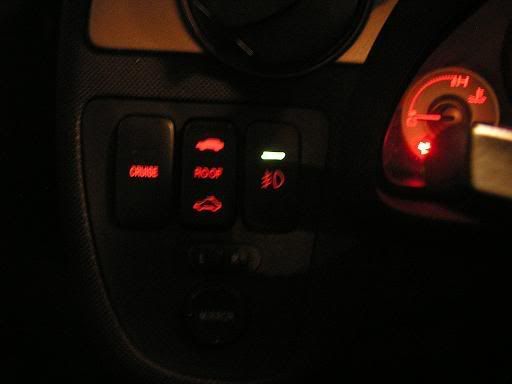
Reattach the negative battery terminal. With the parking or head lights on, the switch backlight should glow, and pressing the button should toggle both the fog lights and the green indicator. If you are unsure which lead is which before final assembly, probe the pins with a multimeter so you solder to the correct terminal instead of trusting wire color.
10 Cure a backlight that stays on constantly
Some harnesses leave the red illumination lit the entire time the car is running. To make the backlight follow the dash dimmer instead, tap the switch's illumination feed into a nearby switched-illumination source such as the cruise control or sunroof button. On the cruise control connector, the red wire with a black stripe is the dimmer-controlled +12 V illumination feed, located at the middle terminal; run the fog switch illumination lead to it.
Pro Tips
- 💡 For a cleaner setup you can unplug, build a proper OEM-style pigtail instead of soldering directly to the switch: connector 04321-SR3-306 (5P 090 F) with pigtail pack 04320-SP0-B00 (red) or 04320-SP0-A00 (yellow). One pigtail pack is enough; the two colors differ only slightly in gauge, so mark the wires yourself and skip buying both.
- 💡 The fog switch is shared across roughly 2002-2006 RSX. An 02-04 switch works on an 05-06 car even when a dealer lists it only for the earlier years.
- 💡 If you only want basic on/off and do not care about the switch backlight, connecting just pin 2 and pin 5 will run the fogs, but the fog icon and green indicator will not illuminate.
- 💡 The OEM switch is inexpensive (around $15) from an Acura dealer or acuraoemparts.com.
- 💡 Confirm each pin's function with a multimeter before soldering rather than relying on wire color alone.
Was this guide helpful?
