Trunk CCFL (Cathode) Accent Lighting Install with 3-Position Selector
Introduction
This guide covers adding a pair of 12-inch cold-cathode (CCFL) tubes inside the trunk of an 8th-generation Honda Accord for accent and utility lighting. The install taps the existing trunk-lamp feed rather than running a fresh circuit, and optionally routes it through a small selector switch so you can choose the factory bulb, the cathode tubes, or nothing at all - handy if you want the glow most of the time but a clean stock look on occasion. Expect roughly a couple of hours if you build the full switched version, most of which is soldering, heat-shrinking, and verifying the switch behavior; a stripped-down always-on version can be done in minutes. Basic soldering skill is the main prerequisite. Adapted from a community writeup by mnkyman on DriveAccord (https://www.driveaccord.net/threads/diy-trunk-cathodes.9635/), including corrections from the follow-up discussion.
Reference
Tools Required
- Soldering iron and thin electrical solder
- Heat gun or hair dryer (to shrink tubing)
- Wire strippers and scissors
- Pliers
- Crimping tool (optional; pliers will do)
- Flat-head screwdriver
- Black zip ties
- Black electrical tape
Parts Required
-
12-inch CCFL (cold-cathode) light kit with inverter box
-
Wire rated for at least 12 volts (speaker wire works)
-
Heat-shrink tubing
-
6-pin selector switch, 2 input / 4 output (optional, for the 3-position setup)
-
Small spade/blade terminals sized to the switch pins
-
3M double-sided automotive tape
Safety Warnings
- ⚠ Pull the interior-lights fuse (fuse 6, 7.5 A) before working; the trunk-lamp feed is live and can short against the bodywork.
- ⚠ CCFL inverter boxes have a known tendency to fail - users report computer-sourced inverters burning out - so use a decent kit and keep the inverter ventilated.
- ⚠ Insulate every exposed conductor, especially at the factory bulb connector, so nothing can short against the metal channel or the adjacent leads.
Step-by-Step Instructions
1 Choose the kit and decide on a switch
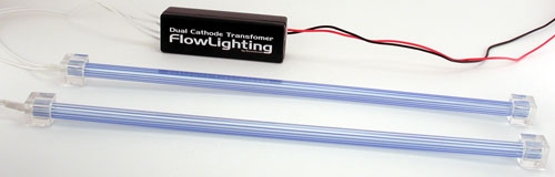
Pick a 12-inch CCFL kit that includes an inverter box; computer-case and automotive CCFL kits both work. A single tube is usually plenty of light for a trunk, and later posters noted that a dual-tube setup can look overly bright once the inverter reaches full output, so choose accordingly. Decide up front whether you want the optional 6-pin selector switch (two input pins, four output pins) that lets you toggle between the stock bulb, off, and the cathodes; if you skip it the tubes simply run whenever the trunk lamp would normally light.
2 Cut power to the trunk lamp circuit
Before touching any wiring, remove the interior-lights fuse (fuse 6, 7.5 A) so the trunk-lamp feed is dead while you work. The original writeup claimed the fuse must go back in the same orientation or it will blow; two follow-up posters corrected this - standard blade fuses are not polarized, so their direction on reinstall does not matter electrically. Note the slot position anyway so reassembly is tidy.
3 Remove the factory trunk light
Insert a flat-head screwdriver at one edge of the lamp housing, press in the retaining tab, and work the whole unit free of its opening. Unplug the blue factory connector from the back of the lamp and set the lamp and lens somewhere safe.
4 Expose and free the trunk-light power lead
Peel back the foam and hard-plastic covering on the harness to expose bare wire - allow for stripping back a generous length, more than seems necessary at first. Cut the blue connector off the feed wire but leave a tail long enough to solder to later. Then pull the power lead up out of the top of the sheet-metal channel and trace it back toward its source at the rear of the trunk so you have slack to work with.
5 Extend and route the power feed
Solder an added length of your 12-volt wire onto the end of the freed power lead and cover the joint with heat-shrink. Route the extended wire neatly around the trunk, using black zip ties to keep it tidy, and feed it back through the hole in the metal channel where the switch and other leads will gather.
6 Build the terminal ends for the switch
The small terminals that fit this switch are still slightly wider than its pins, so squeeze each one gently with pliers, then ease it open again with a small flat-head until it grips the pin snugly. Slide a piece of heat-shrink onto the wire first, insert the conductor into the back of the terminal, and crimp it down with a crimp tool or pliers; shrink the tubing over the joint to finish. Always position the heat-shrink before crimping.
7 Make the stock-light jumper and reinstall the lamp
Fabricate a short jumper for the factory bulb: solder the blue connector (with heat-shrink) to one end of a length of wire and put terminals on the other end using the method above. Route this jumper through the metal channel so the terminal end emerges alongside the power feed while the blue-connector end comes out at the trunk-lamp opening. Plug the blue connector back into the factory lamp and reseat the lamp in its housing.
8 Build the cathode harness and mount the inverter
Make a third cable with terminals on one end and, on the other, the connector that mates to the cathode inverter box. Route it through the metal channel to join the other leads. Mount the inverter inside the channel with 3M double-sided automotive tape; if the inverter has ventilation slots, orient them upward and set the box low in the channel so those slots stay clear for cooling.
9 Mount the tubes
Fix the cathode tubes along the sheet-metal channel with zip ties. Where a tube contacts bare metal, pad the contact point with 3M tape to stop it from rattling - the trunk's low-frequency speakers sit nearby and will otherwise buzz against the tubes.
10 Wire the selector switch
The two central pins are the inputs and the four outer pins are the outputs. Land the power-feed terminals on the two center pins. Connect the stock-light pair to one outer pair of pins and the cathode pair to the other outer pair. Before energizing, confirm that no bare conductor can touch another or the bodywork, paying particular attention to the exposed factory bulb connector. Reinstall fuse 6 in its original slot.
11 Test operation and confirm polarity
Work the switch through its positions and verify all three states: factory bulb on, everything off, and cathodes on. Because the switch energizes the side opposite to where it is pushed, flip it each way to identify which outer pins are positive and negative and to confirm the tubes light. If nothing works, recheck the terminal-to-pin connections - sorting out the switch orientation can take a couple of tries.
12 Secure the wiring and tidy up
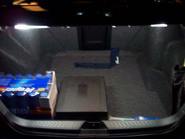
Wrap electrical tape around the terminals and switch body to hold everything in place. Tuck the leftover wire back through the opening into the hollow section of the channel until only the switch protrudes, tucked out of sight. Do a final check that nothing is pinched or shorting, then close up.
Pro Tips
- 💡 For a fully reversible install that keeps the factory harness intact (and avoids warranty concerns), leave the blue connector in place and tap into the tube's own leads instead of cutting the connector off, as several later posters preferred.
- 💡 The selector switch is optional. A basic always-on version needs little more than cutting the kit's own connector, joining the wires, and taping the tubes down - only a few minutes of work.
- 💡 Soldering gives the most durable joints, but automotive wire taps from a parts store are a workable no-solder alternative.
- 💡 A single tube is usually enough for a trunk; dual tubes can be too bright once the inverter fully charges.
- 💡 Mount the inverter with any vent holes facing up so it can cool properly.
Was this guide helpful?