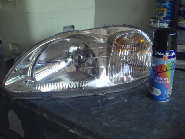
Honda Prelude (5th Gen) Blinking Side Marker Wiring
Introduction
On the fifth-generation Honda Prelude (BB6), the fender side marker lights are not wired to switch with the factory lighting the way earlier generations are, so a small wiring circuit is needed to make them behave like proper markers. This guide wires each side marker so it glows steadily with the parking (running) lights and flashes in time with the turn signal on the same side. The trick is a single SPDT relay per side that normally passes running-light power through to the marker bulb and momentarily interrupts that feed every time the turn signal pulses. The work involves splicing into the existing bumper marker and turn-signal circuits, so it suits anyone comfortable with basic 12V wiring and quick-splice connectors. It applies to the 1997-2001 Prelude and works whether your fender markers were factory-cut or added as a custom installation. Adapted from a community writeup by 98BB6SH on PreludePower (https://www.preludepower.com/threads/diy-5th-gen-side-markers-that-blink-fender-lights.304972/), including corrections from the follow-up discussion.
Reference
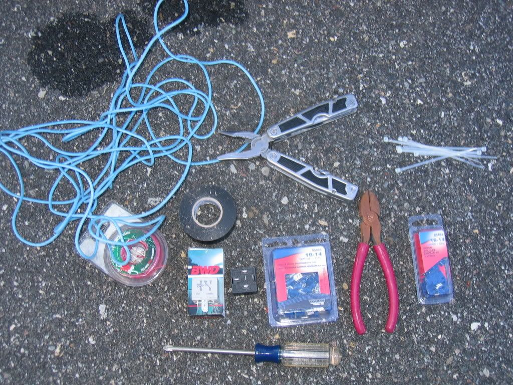
Tools Required
- Phillips head screwdriver
- Wire stripper
- Crimping tool or pliers
- Electrical tape
- Zip ties
Parts Required
-
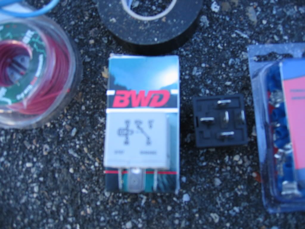
2 SPDT (single pole, double throw) relays
-
Quick-splice connectors (several)
-
Female quick-connect terminals
-
Extra primary wire (red for power runs, black for ground)
-
Fender-mounted side marker light assemblies with bulbs (if not already fitted)
Safety Warnings
- ⚠ You are splicing into live 12V circuits; insulate every quick-splice and connection completely to avoid a short or blown fuse.
- ⚠ The turn signals only operate with the ignition in the accessory or on position, so test with the key turned before assuming the wiring failed.
Step-by-Step Instructions
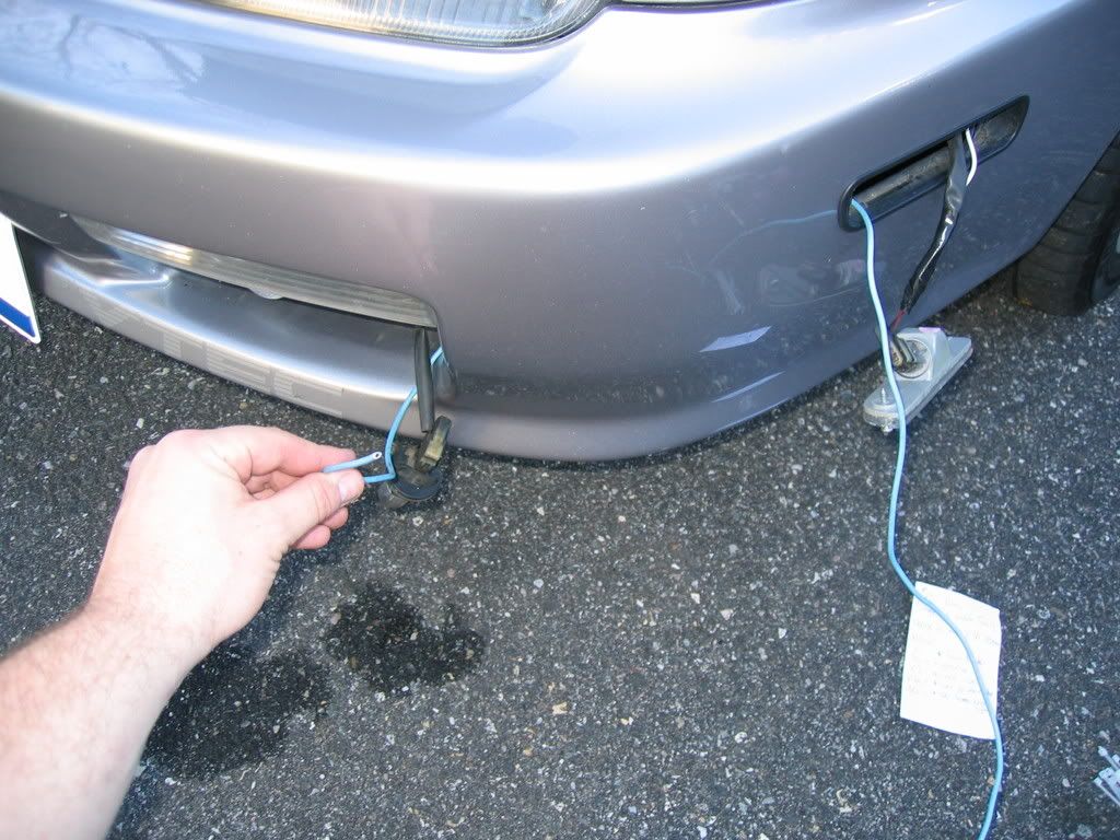
1 Remove the bumper marker lamp
Take out the retaining screw that holds the bumper-mounted marker light, then draw the lamp forward out of its opening. Let it hang so the plug and its wiring are exposed and reachable from the front of the bumper.
2 Remove the turn signal lamp
Working through the lower grille opening, back off the screw that secures the front turn signal lamp and free it from the bumper. With both the marker lamp and the turn signal now out, you can access the connector and wiring for each from a single area.
3 Identify the power and ground wires

Inspect each connector. Both the bumper marker plug and the turn-signal plug carry two wires: a green wire, which is the switched power feed, and a black wire, which is the ground. Confirm this on both circuits before cutting anything.
4 Tap a feed from the turn signal

Cut a length of wire roughly two feet long so it easily reaches between the lamps; the slack is trimmed later. Attach one end to the green power wire of the turn signal using a quick-splice connector and crimp it closed. This is the flashing feed (the blue-dot wire in the reference photos). The simplest routing is to push this wire from the marker opening through the bumper cavity and out to the turn-signal location, reaching in where the turn signal sat to catch it.
5 Tap a feed from the running-light power

With another quick-splice connector, branch a wire off the green power wire of the bumper marker light. This constant running-light feed is the red-dot wire. Prepare a separate wire that will carry power out to the fender marker bulb itself; this is the white-dot wire in the reference photos.
6 Tap the ground

Using one more quick-splice connector, branch a wire off the black ground wire at the bumper marker light. This is the black-dot ground feed. At this point four leads should emerge from the marker opening: red (running-light power), white (out to the marker bulb), blue (turn-signal power) and black (ground).
7 Wire the SPDT relay
Land the four leads on the numbered relay terminals. Terminal 30 receives the constant running-light feed (red dot). Terminal 87A sends +12V out to the fender marker bulb (white dot). Terminal 85 receives the turn-signal feed (blue dot). Terminal 86 goes to ground (black dot). Leave terminal 87 unused. In this arrangement running-light power reaches the bulb through the normally-closed 87A path, keeping the marker lit, while each turn-signal pulse energizes the coil and breaks that feed so the marker flashes. This terminal assignment was corrected in the follow-up discussion (credit LilMsPrelude).
8 Test the circuit

Before buttoning anything up, verify operation. Turn the key to the accessory position, since the turn signals are dead otherwise. Switch on the parking lights and confirm the fender marker glows steadily, then operate the turn signal and confirm the marker flashes in sync on that side.
9 Insulate and secure

Once operation is confirmed, wrap every splice thoroughly with electrical tape to prevent shorts. Bundle the wiring with zip ties and weatherproof the relay; wrapping it inside a cut rubber-glove fingertip before taping seals it well. Tuck the relay into the bumper cavity or the marker opening and reinstall both the turn signal and the bumper marker lamp.
10 Repeat on the opposite side

Carry out the same procedure for the marker and turn signal on the other side of the car, using the second SPDT relay. Each side is wired independently so that its marker flashes only with its own turn signal.
Pro Tips
- 💡 Run the connecting wire long (about two feet) and feed it from the marker opening through the bumper to the turn signal; the routing is far easier that way, and you can trim the excess afterward.
- 💡 Use a distinct wire color for each of the four circuits so the power, ground, marker-out and turn-signal leads stay easy to tell apart.
- 💡 If you only want the markers to glow constantly without flashing, you can skip the relay entirely: ground the marker to the chassis and tap its power straight off the bumper light (method shared by jdmtyperaccord in the thread).
- 💡 The relay is small enough to hide almost anywhere behind the bumper once it is wrapped; the marker opening itself makes a convenient tuck point.
Was this guide helpful?