Honda Fit (GE8) Ground Wire Upgrade
Introduction
Adding supplemental ground straps to a second-generation Honda Fit (GE8) gives the charging system lower-resistance return paths between the battery, engine block, transmission, and chassis. The goal is to reduce voltage sag under load: the owner in this thread was bothered by headlights dimming and idle climbing toward 1000 RPM whenever the air conditioning or radiator fans engaged, and reported that the extra grounds noticeably calmed both. The whole job uses about ten dollars of wire and terminals and requires no cutting of factory harnesses. It applies to the GE8 Fit but the same approach transfers to most Honda four-cylinders. Adapted from a community writeup by kurisux92 on FitFreak (https://www.fitfreak.net/forums/2nd-gen-ge8-specific-fit-engine-modifications-motor-swaps-ecu-tuning-sub-forum/73026-diy-grounds.html), including corrections from the follow-up discussion.
Reference
Tools Required
- Digital multimeter (DVOM) for checking resistance/voltage drop
- Dremel or rotary tool with an abrasive bit (sandpaper or a wire brush also works)
- Wire crimper or crimp/solder tool for ring terminals
- 10mm socket or wrench
- Basic hand tools and wire cutters
Parts Required
-
Roughly 8 feet of 10-gauge automotive-grade copper wire
-
Ring terminals sized to fit the 10-gauge wire and the anchor bolts
-
Reuse the factory washers and bolts at each anchor point
Safety Warnings
- ⚠ Always disconnect the negative battery cable before working on grounds or near the battery terminal.
- ⚠ Route and secure every strap away from the drive belt, pulleys, and hot exhaust so nothing can be pulled into moving parts.
- ⚠ The ECU resets when power is removed; idle and throttle response may feel off until it completes a short relearn drive.
Step-by-Step Instructions
1 Disconnect the negative battery cable
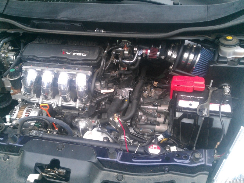
Before touching any grounding hardware, loosen and remove the negative battery terminal and set the cable aside so it cannot spring back onto the post. This isolates the electrical system while you work near the block and chassis. Be aware that removing power clears the ECU's learned values, so idle and throttle behavior will need a short relearn drive once everything is reconnected.
2 Cut and terminate the ground straps
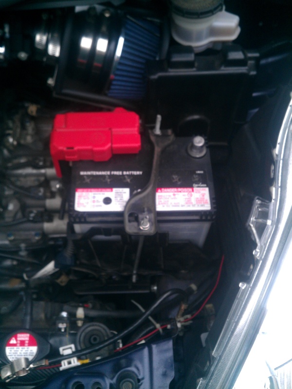
Measure and cut lengths of 10-gauge wire to reach each intended anchor point with a little slack for routing. Crimp a ring terminal onto both ends of every strap, sizing the ring to the bolt it will sit under. Automotive-grade wire and terminals are worth using here since the straps live in the engine bay heat and vibration.
3 Locate solid ground points with a multimeter
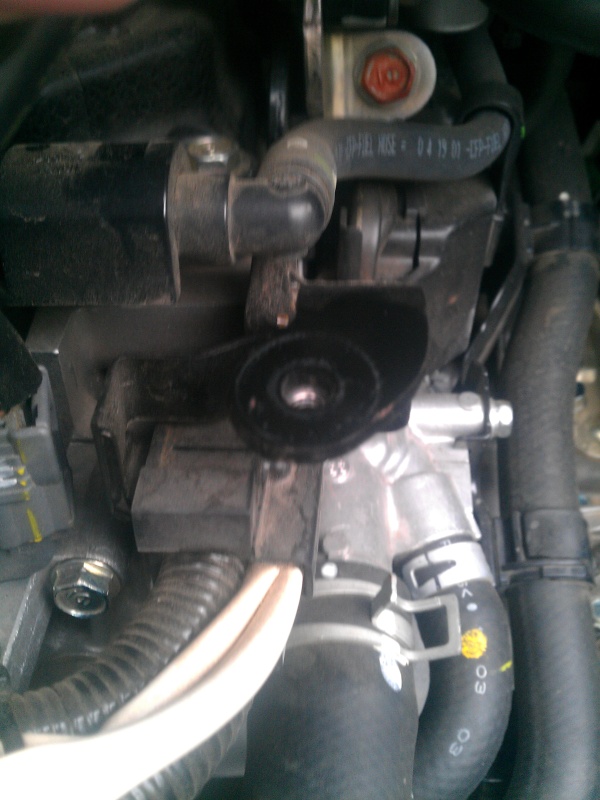
Use a DVOM (a Fluke was used here) to find bolt locations that read low resistance back to the battery negative. A clean chassis point measured about 0.3 ohms or less to the battery negative, confirming the body itself is an effective conductor once the connection is clean. Pick anchor bolts on the block, on the transmission, and on the chassis that give you convenient, low-resistance targets.
4 Ground the engine block to the chassis

At the block anchor bolt, strip the paint and coating down to bare metal with the Dremel so the ring terminal seats against raw steel; paint is an insulator and will ruin the connection. Bolt one end of a strap to the cleaned block point and run the other end to a bare chassis point, using the factory washers and bolts. The clarification from the discussion is that 'roughing it up' simply means removing paint, not leaving a rough surface.
5 Add a battery-to-chassis ground
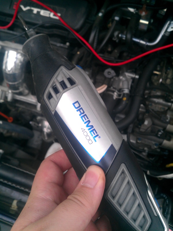
Attach a ring terminal at the 10mm nut on the negative battery post and run this strap to a solid chassis bolt. The bracket on the side that holds the ECU makes a convenient anchor. Note that the common practice is to tie these upgrade grounds to chassis points rather than piling several wires directly onto the battery post, and there is limited room on the factory terminal in any case.
6 Add a transmission-to-chassis ground
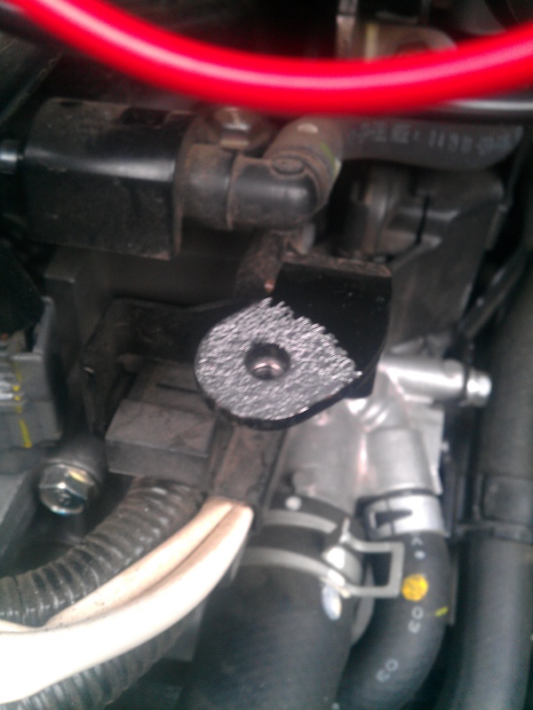
Use the bracket that secured the factory airbox and bolts to the transmission as the transmission anchor. Clean the contact face with the rotary tool the same way, then bolt the strap down with the factory washers and hardware and route the other end to a bare chassis point. This gives the transaxle its own dedicated return path.
7 Secure the wiring, reconnect, and verify
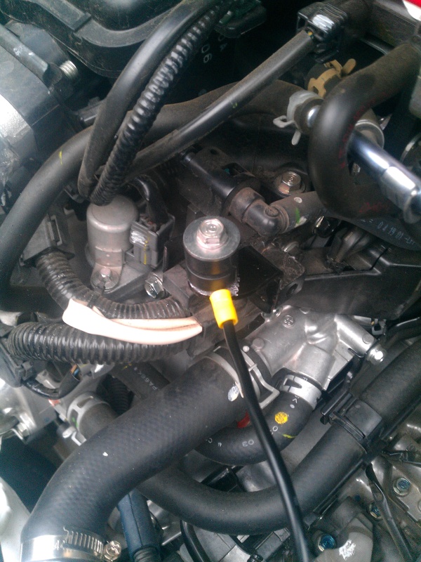
Confirm every ring terminal is torqued down onto clean metal, then route and tie the straps so they stay clear of the belt, pulleys, exhaust, and any moving or hot parts. Reconnect the negative battery cable last. Expect the ECU to relearn idle over the next several minutes of driving. Optionally recheck resistance from the battery negative to each new point to confirm a low reading.
Pro Tips
- 💡 Removing paint down to bare metal at every anchor is the single thing that makes or breaks the connection; a strap bolted over paint accomplishes nothing.
- 💡 A dab of dielectric grease on the finished joint can slow future corrosion at the contact point.
- 💡 Chassis steel measured only about 0.3 ohms to the battery negative, so well-cleaned body grounds perform nearly as well as a dedicated copper run.
- 💡 Reported result on the GE8: headlight dimming when the A/C or cooling fans switch on was greatly reduced and idle stayed steadier instead of jumping toward 1000 RPM.
Was this guide helpful?
