Honda Fit (GE) Satellite Radio Installation
Introduction
This guide covers installing a satellite radio receiver, such as a Sirius Sportster, in the second-generation Honda Fit, with notes that also apply to the earlier GD chassis. It walks through pulling the factory head unit far enough to route cabling cleanly, adding a dedicated 12V accessory outlet to power the receiver, mounting the antenna on the roof and routing its cable into the cabin through the hatch, and feeding audio to the head unit's auxiliary input. The aim is a tidy result with almost no visible wiring rather than a plug hanging loosely from the dash. Because many current satellite receivers step 12V down to 5V through a transformer built into their supply cable, a dedicated outlet keeps the power source correct and flexible for a future receiver swap. Adapted from a community writeup by notorious.dds on FitFreak (https://www.fitfreak.net/forums/2nd-gen-ge8-specific-fit-interior-modifications-sub-forum/36490-how-install-guide-xm-sirius-radio.html), including corrections from the follow-up discussion.
Reference
Tools Required
- Socket extension about 10 in long with a 5/16 in socket
- 3/8-to-1/4 in socket adaptor
- Large flat-blade screwdriver
- Mini pry bar for interior trim
- Masking tape
- Wire crimping tool
- Wire cutters and strippers
- Bent coat hanger to fish the antenna lead
- Drill (only if fastening a second accessory outlet)
Parts Required
-
Satellite radio receiver and vehicle dock (e.g. Sirius Sportster)
-
One or two 12V accessory power outlets
-
Insulated female spade terminals and uninsulated male terminals
-
Inline fuse holder with fuse
-
Magnetic-base satellite antenna
-
Audio cable to the head unit AUX input (right-angle plug preferred)
-
ARKON Sr-53 14 in Windshield S-Pedestal Mount (optional alternative mount)
Safety Warnings
- ⚠ Do not remove the seat belt anchor bolt to route wiring unless you know its torque specification and have a proper torque wrench to reinstall it correctly.
- ⚠ Use extension wire of a gauge equal to or heavier than the wire being extended; undersized wire can overheat and start a fire if the outlets are overloaded.
- ⚠ Fuse any added always-connected outlet leg, as its wire may fail at a lower current than the main outlet circuit fuse.
- ⚠ Work on the power outlets with the key out of the ignition; disconnect the battery if you are concerned about your safety or electronics.
Step-by-Step Instructions
1 Pull the factory head unit from the dash

Free the stereo so cabling can be routed behind it. A single fastener tucked beneath the unit is usually the awkward part; reach it with a roughly 10 in extension carrying a 5/16 in socket, joined through a 3/8-to-1/4 in adaptor. Turn it by hand with no ratchet attached, because the ratchet head will not clear the gap between the panel opening and the cupholder beneath it. The manufacturer publishes PDF removal instructions for both the 2009 GE and the earlier GD chassis; following them helps avoid cracking the trim.
2 Release the trim without the factory tools
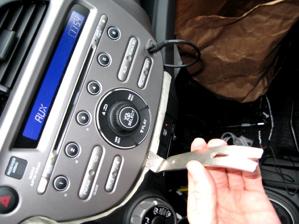
The service PDF calls for two Honda trim tools that most home installers do not own. Instead, lay masking tape at the points the PDF marks to protect the finish, then start the panel at the notch inside the upper glovebox using the widest flat screwdriver that fits. As soon as the unit lifts slightly, switch to a mini pry bar to work it the rest of the way out; the same bar handles the other interior panels this job touches.
3 Add a dedicated accessory outlet for the receiver

Rather than occupy the factory 12V socket, which blocks a cupholder whenever a plug is inserted, add one or two accessory outlets while the console is open. Many receivers run on 5V and depend on a transformer built into their power lead, so feeding them from a proper 12V outlet keeps the wiring correct and leaves room to change radios later. If your receiver needs any voltage other than 12V, you must either provide such an outlet or build a transformer into the supply line.
4 Build a fused power extension and splice in the outlets

The lead feeding the factory outlet has almost no slack, so unplug it and lengthen it with a short jumper. Cut about 8 in from both the red and black leads of a spare outlet, crimp an uninsulated male terminal on one end of each and an insulated female terminal on the other, and use the pair as an extension. Splice the added outlets onto this jumper. Fit an inline fuse on the leg feeding an always-connected outlet, since that wire can fail below the rating of the main outlet circuit. Keep the extension wire gauge equal to or heavier than the wire it lengthens. A receiver leg generally needs no extra fuse, because these radios draw under 2A and their supply cable already carries one.
5 Mount the antenna on the roof

Pick a flat area of the roof so the magnetic base grips firmly; toward the outer edge the panel curves and the magnet holds poorly. Plan the cable path to avoid pinch points. On the Fit the hatch closes tightly against the body along its whole upper edge except at the corners, and ice building up in that channel can crush a cable routed through it. Keep the wire clear of those areas.
6 Feed the antenna cable into the cabin through the hatch boot

Peel back the rubber grommet at the upper-left corner of the hatch opening together with the adjacent inner trim panel. Push a bent coat hanger out through the grommet hole, hook the antenna lead, and draw it inside, then pull the remaining cable through. Route it so the wire enters below the grommet rather than above, and leave a small drip loop underneath so water sheds off instead of tracking into the body. Tuck the roof portion under nearby trim to keep it steady.
7 Route the cable forward to the head unit
Lead the antenna wire toward the dash by tucking it between the headliner and the side trim, or under the door weatherstripping as it passes the rear and front openings, until it reaches the lower-left corner of the dash. Remove the driver's-side lower dash panel: rotate its plastic retaining knob 90 degrees to free the left side, then pull the panel down and toward the seat to release the right side. Lay the wire across the two exposed steel braces, then guide it upward behind the dash so it emerges beside the stereo along its right-hand edge.
8 Mount the receiver and connect it
Secure the dock and connect the antenna, power, and audio leads. A large-diameter suction-cup mount holds far better in cold weather than the small cup supplied in a typical car kit; the ARKON Sr-53 14 in Windshield S-Pedestal Mount stayed attached even at 4 degrees Fahrenheit. Run the audio lead to the head unit AUX input, where a right-angle plug sits flatter than a straight one. Tuck any surplus cabling back into the opening near the stereo's upper-right corner so the unit seats fully.
9 Reassemble and test
Bundle and stow the slack, then press the head unit back into place while watching that no wire is trapped between it and its housing. Refit the lower dash panel and any other trim removed earlier. Power up the receiver and confirm clean audio through the AUX input along with a solid antenna signal before calling the job done.
Pro Tips
- 💡 A simpler no-cut option for a second outlet is a plug-in splitter from an electronics store; it adds some cable clutter but avoids any wiring work.
- 💡 The receiver can instead be mounted with a suction cup on the small triangular driver's-side window, hiding the leads under the door trim along the base of the dash.
- 💡 If a side-window mount will not swivel far enough toward the driver, reverse the connecting arm that joins its suction cup to the dock; the reversed curve looks wrong yet frees up extra rotation.
- 💡 The antenna also works mounted under the hatch behind the weatherstripping, hidden when the hatch is closed, with reception reported as strong.
- 💡 A handheld remote makes channel changes easy when the receiver sits farther from the driver.
Was this guide helpful?
.JPG)
