Acura RDX (1st Gen) Spark Plug Replacement and Top-Mount Intercooler Removal
Introduction
The first-generation Acura RDX (2007-2012) uses a turbocharged 2.3-liter engine fitted with a top-mounted charge air cooler (intercooler) that sits directly over the cylinder head. Because that cooler blocks all access to the ignition system, replacing the four spark plugs first requires lifting the intercooler out of the way. This guide covers the complete job: detaching and removing the charge air cooler, swapping the factory NGK laser iridium plugs, and reassembling everything to the correct torque values. Honda schedules these plugs for roughly 100,000 miles, and owners who have opened the engine at that interval consistently report the originals still in serviceable shape, so the work is as much inspection as replacement. Two proven ways to release the cooler's bypass valve are described, since the community settled on the simpler one after the original writeup. Adapted from a community writeup by 737 Jock on AcuraZine (https://acurazine.com/forums/1g-rdx-diy-faq-161/diy-remove-charge-air-cooler-replace-spark-plugs-792921/), including corrections from the follow-up discussion.
Reference
Tools Required
- Straight-tip (flat) screwdriver
- Ratchet
- 305mm (12 in) socket extension with a locking mechanism
- Flexible coupling / universal (swivel) joint
- 10mm socket (1/4-inch drive recommended for tight rear bolts)
- Long-reach needle-nose pliers
- Hose-clamp pliers
- Hose pick (helpful)
- Hose separator tool (helpful)
- 5/8-inch spark plug socket with rubber insert
- Torque wrench
- Magnetic pickup or magnet for the extension (helpful)
Parts Required
-
NGK SILKR8A-S laser iridium spark plugs, NGK stock no. 1402 (qty 4)
-
Dielectric silicone grease
-
Anti-seize compound
-
Silicone grease for hose and pipe fittings
-
Masking tape
Safety Warnings
- ⚠ Let the engine cool completely before removing any plug; hot aluminum head threads strip easily.
- ⚠ Never touch or lean on the intercooler fins, even a light touch bends them and reduces cooling.
- ⚠ Tape over the turbocharger outlet the instant the cooler is off; any dropped debris can destroy the compressor wheel.
- ⚠ Do not overtighten the plugs. 18 N-m is a light setting reached in about half a turn; going past three-quarters of a turn risks damaging the plug or the threads.
- ⚠ Disconnect the negative battery cable before starting, and remember all DIY work is done at your own risk.
Step-by-Step Instructions
1 Cool the engine and disconnect the battery
Let the engine sit until it is completely cold; working hot cylinder-head threads greatly raises the chance of stripping them. Raise the hood and set the prop rod in its upright service position for full working room. Loosen the 10mm negative battery terminal and set the cable aside so nothing can arc or wake a circuit while you work. Throughout the procedure, treat 'left' as the driver side and 'right' as the passenger side, referenced to the car itself rather than to where you happen to be standing.
2 Remove the plastic engine cover
Give each of the four quarter-turn fasteners on the engine cover a quarter rotation with a large flat screwdriver (a coin also works) and lift the cover off. From here on, treat the exposed intercooler fins as fragile: even a light bump bends them, which hurts cooling efficiency, so keep tools and hands clear of them.
3 Unbolt the charge air cooler
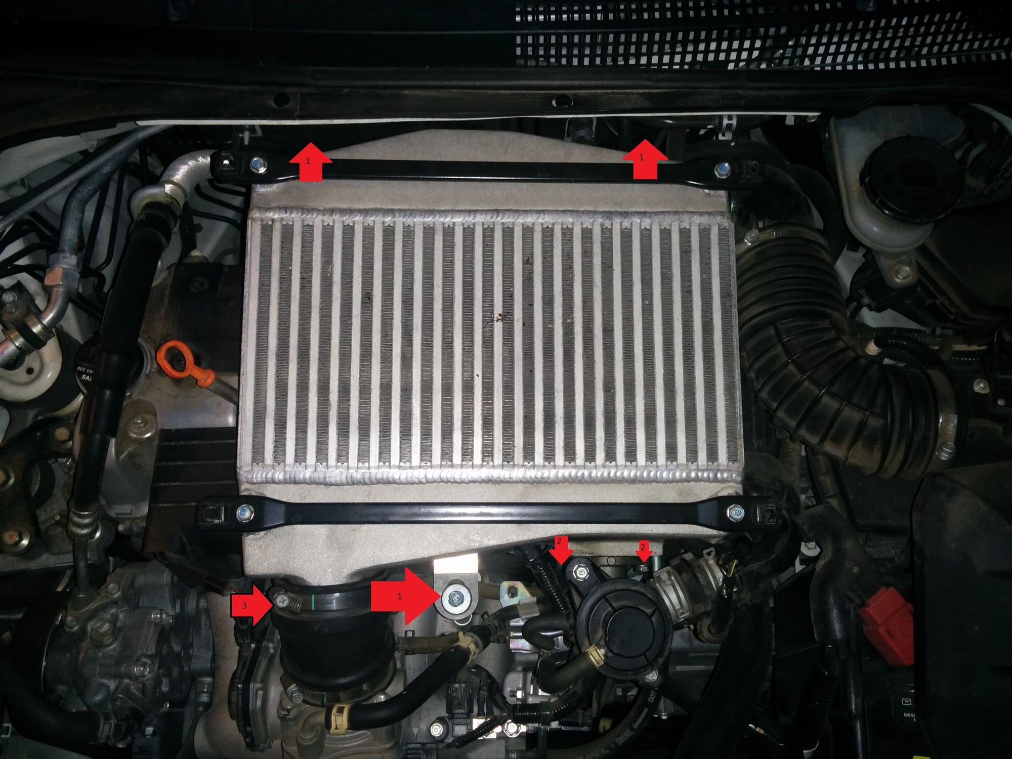
Remove the 10mm hex bolts securing the cooler. One sits at the front and one on the right, which is easiest to reach with the long extension. Two more are on the left; the rearmost needs the flex coupling plus extension to clear the surrounding parts, and a shorter bolt on that side only pins the intake duct to the cooler. Later contributors flagged an extra bolt on the right and found that 1/4-inch drive tools with a universal joint reach the tight rear fasteners far more easily than bulkier 3/8-inch gear. Drop each bolt into a labeled bag so it returns to the correct hole.
4 Release the bypass valve (two methods)
The bypass control valve stays attached to the cooler, but its links to the car must come off. The original method releases five items in turn: the boost sensor electrical plug (press its top tab, ease it off, then unclip its wiring from the bypass pipe), the bypass outlet pipe with its spring clamp, the upper and lower bypass control hoses, and finally the awkward vacuum hose low on the assembly. Use hose-clamp pliers to hold each clamp open, a pick or separator to break the seal, and gentle back-and-forth rotation to walk each hose off its barb. The discussion later found an easier route: rather than pulling the hoses, undo the two 10mm bolts holding the valve body to the cooler and lift the cooler with the valve still plumbed. If you do that, keep track of the orange spacer/rubber gasket between the valve and the cooler.
5 Loosen the outlet-pipe clamps
At the rear of the cooler, back off the upper 10mm clamp on the turbocharger outlet pipe and let it slide down the pipe; the flex coupling and extension make it reachable. Note the painted clamp-position marks before disturbing anything. Then loosen the clamps on the charge-air outlet pipe at the front. A tip from the discussion: rotate the turbo outlet clamp so its screw faces the passenger side, which frees up much more finger room at the next service.
6 Lift out the cooler and protect the turbo

With every clamp, hose, and bolt released, ease the cooler free, front edge first off the charge-air outlet pipe, then rearward out of the turbocharger outlet. Handle it only by the frame and sides and keep off the fins. The moment the cooler clears the turbo pipe, cover that open pipe with tape so nothing can drop into the spinning compressor wheel. Inspect the fins and gently comb any bent ones straight with a fin rake or a fine flat blade.
7 Expose the ignition coils
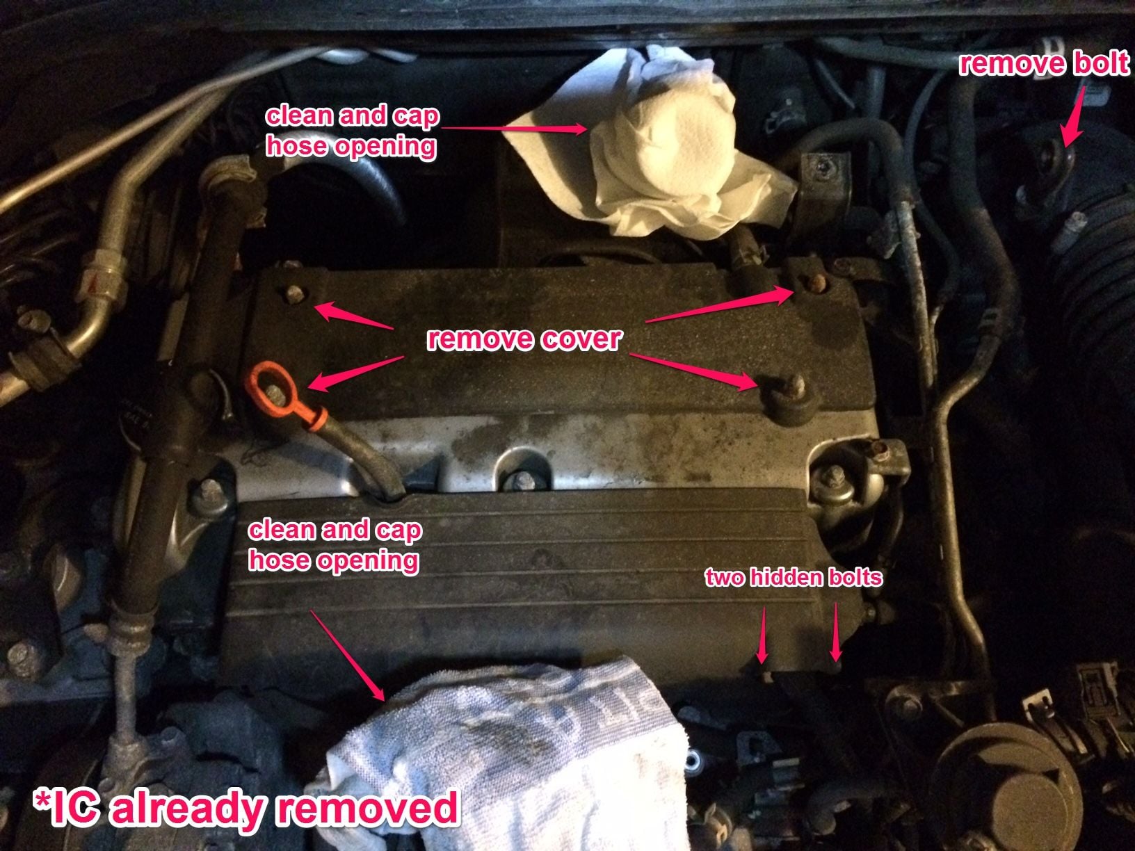
Undo the four 10mm bolts on the spark plug cover and lift it away. Underneath sit the four ignition coils, each capped by a blue electrical connector. The fuel rail cover can stay in place; it is not in the way of plug work.
8 Remove the coils and clean each well
Pull the coils one at a time, working left to right and beginning with the leftmost, which is the least obstructed. Squeeze the release tab on the front of each blue connector, unplug it, take out the coil's single 10mm bolt, then wiggle and rotate the coil upward until it frees from the plug. Before pulling each plug, blow or vacuum the well clean so grit cannot fall down the open threads, a correction the author accepted from a reader. Set each coil aside safely; the four are interchangeable, so keeping them in order is unnecessary.
9 Extract and inspect the old plugs
Fit the 5/8-inch plug socket with its rubber insert onto the extension and lower it until it clicks onto the plug; the rubber liner grips the plug for removal. Use an extension that positively locks: one owner had the socket separate and stay down the well after torquing, taking several minutes to fish out, and a magnet helps hold the assembly together. Inspect each plug. Honda's serviceable range is 0.7mm to 0.8mm (0.028"-0.031") and any plug with rounded electrode edges is due. A typical original pulled near 78,000 miles had opened to 0.81mm with worn, rounded electrodes yet still showed a dry medium-brown color and sound insulator.
10 Prepare and install the new plugs
Use NGK SILKR8A-S laser iridium plugs (NGK stock no. 1402). They arrive pre-gapped at about 0.711mm (0.028") and must not be checked or adjusted with a feeler gauge, which scrapes the iridium off the electrode and ruins the plug. Wipe the ceramic insulator with a thin film of dielectric grease, apply a light coat of anti-seize to the threads, and snap the plug firmly into the socket. Lower it straight into the well and turn it in by hand until the threads catch; never begin a plug with a wrench. If it binds at all, back it out and restart rather than cross-thread the head. Once it seats hand-tight on the washer, torque to 18 N-m (13 ft-lb / 156 in-lb). At the right setting the wrench clicks within roughly half a turn of first contact; if it has not by three-quarters of a turn, stop and investigate.
11 Refit the coils and spark plug cover
Reinstall the coils in reverse order, right to left. Seat each one over its plug, click the blue connector back on, push it home, and snug the 10mm bolt to 12 N-m. Set the spark plug cover back down and tighten its bolts to 9.8 N-m.
12 Reinstall the charge air cooler
Peel the tape off the turbo outlet and any hoses you plugged. Lightly grease the pipe and hose sealing surfaces with silicone, keeping it out of the openings, then guide the cooler back in, turbo outlet first, followed by the front outlet pipe and throttle-body connection. It takes patience, and the front hose in particular tends to resist; several owners found it easier to fit a stubborn hose onto the cooler first and install them together. Align the mounting holes and tighten the cooler bolts to 12 N-m. Return each clamp to its marked spot and tighten only until the clamp end meets its painted stop line; if it passes the line the clamp is stretched and should be replaced. Finally, reconnect whatever you removed at the bypass valve (either the five fittings, starting bottom-up with the vacuum hose, or the two valve bolts), then reconnect the battery.
Pro Tips
- 💡 The pre-gapped iridium plugs must not be gapped; forcing a feeler gauge in snaps the fine electrode and ruins the plug.
- 💡 Many owners skip disconnecting the five bypass hoses by simply removing the two 10mm bolts that hold the valve to the cooler; just keep the orange spacer/gasket.
- 💡 1/4-inch drive sockets, a universal joint, and a magnetic extension reach the tight rear bolts far more easily than 3/8-inch tools.
- 💡 Rotate the turbo-outlet clamp so its screw faces the passenger side to gain much more room at the next plug change.
- 💡 The four coils are identical and their leads are too short to swap positions, so labeling them is not needed.
- 💡 The NGK plugs are widely sold by parts retailers for roughly $10-13 each, well under dealer pricing.
- 💡 Choose a socket extension that locks to the plug so it cannot separate and stay in the well after torquing.
Was this guide helpful?