
Installing an S2000 Engine Start Button in a 5th-Gen Honda Prelude
- Disconnect the battery before working if you are not experienced with live automotive wiring.
- If an aftermarket alarm or immobilizer interrupts the starter wire, the new relay must be wired after the immobilizer relay or the immobilizer will be bypassed.
- Do not extend the heavy-gauge contact-side (pins 30/87) wires of the relay base; a poor joint here is a weak point in the starter circuit.
- If you cut the factory start wire to disable key cranking, insulate both cut ends with electrical tape.
Introduction
This procedure retrofits a genuine Honda S2000 engine start button into the cigarette-lighter position of a 5th-generation (1997) Honda Prelude. The button is wired through a new automotive relay spliced into the factory starter circuit, so the car starts exactly like an S2000: insert the key, turn the ignition to ON, then press and hold the button until the engine fires. The key barrel, steering lock and factory immobilizer are all retained, and you can optionally keep or disable the key's START position. The same relay schematic works on any Honda (a follow-up post confirms a JDM Civic Type R button bolts straight into a Civic FD panel with no modification), but the wire colors described here are specific to the 5th-gen Prelude - on any other car, verify every wire with a test light before splicing. Have your stereo security code on hand before starting, because the stereo must be removed. Adapted from a community writeup by ECU-MAN on OzHonda (https://ozhonda.com/forum/showthread.php?42680-DIY-S2000-start-button-into-97-Prelude), including corrections from the follow-up discussion.
Procedure
9 steps-
Step 1: Disconnect the battery and remove the stereo fascia
If you are not confident working around live wiring, disconnect the battery before starting (make sure you have your stereo security code first). Grip the stereo fascia and pull it straight out towards you to unclip it.
-
Step 2: Remove the stereo
Remove the four screws securing the stereo (two on each side). Pull the stereo forward and unplug the antenna lead and the main connector. If the car has a CD changer, unplug that connector as well.
-
Step 3: Remove the cigarette lighter
Rotate the rear of the lighter barrel counter-clockwise (viewed from the rear of the housing) to unscrew it, then unplug the lighter's electrical connector and remove the lighter from the housing.
-
Step 4: Make a template and file the lighter housing to fit the button
Do not rush this step. Trace the outline of the S2000 button onto hard paper and cut the template out, allowing for the locating grooves on the sides of the button. Confirm the template fits the button itself before marking the lighter housing. Transfer the outline to the housing, then file the opening out gradually, test-fitting the button repeatedly so you do not remove too much material. Apply only light pressure - the housing plastic is not very strong. The finished fit should be snug so the button cannot move, and as flush as possible at the front face; the button is retained by this friction fit.
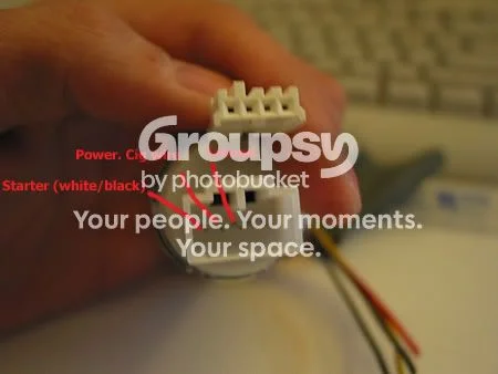
FIG. 2.4 -
Step 5: Locate the starter-signal connector under the dash
Remove the lower dash cover. Under the dash, locate the two-wire connector carrying the start signal and constant power: on the 5th-gen Prelude it has a white wire and a black wire with a white tracer (blk/wht). Unplug the connector and drop it down to a position where you can work on it comfortably. Unsheath the loom covering and expose enough of both wires to solder to. Note: these colors are for the 5th-gen Prelude only - on any other vehicle, confirm the correct wires yourself with a test light before committing.
-
Step 6: Wire the relay switching contacts into the starter circuit
Fit the relay to its base and work with the base wiring. Do not extend the wires on the contact side of the relay base - they are heavy gauge and extending them creates a weak point in the start system. Solder the pin 30 wire of the relay base to the white wire, let the joint cool, and wrap it thoroughly with quality electrical tape. Solder the pin 87 wire of the relay base to the black/yellow wire and insulate it the same way. If the car has an aftermarket alarm or immobilizer that interrupts the starter wire, the relay must be wired in after the immobilizer relay. Optionally, to stop the key from cranking the car (button-only starting), cut the black/yellow wire between the relay joint and the ignition switch and insulate both cut ends with tape - this is purely a matter of preference and the key START position can be retained.
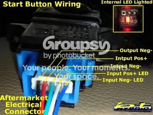
FIG. 2.6 -
Step 7: Wire the relay coil and run wires to the button location
At the under-dash fuse box, locate the ignition (IGN) wire - black with a yellow tracer (blk/yel). Solder a new wire to it and run that wire across to the lighter location beside the stereo. Find a good chassis ground point under the dash: solder the relay base pin 86 wire to ground, and also run a separate ground wire over to the lighter location. Finally, run a wire from relay base pin 85 to the lighter location, soldering it to the pin 85 wire of the base. Make every solder joint neat, insulate with quality electrical tape, then bundle the relay wiring and secure it with cable ties up under the dash, keeping it out of the way. You should now have three wires at the lighter location: ground, IGN (blk/yel), and the relay pin 85 wire.
-
Step 8: Connect the S2000 button plug
Use the floppy-drive power connector as the plug for the back of the S2000 button - ignore the original colors of the connector's wires entirely. Wire it as follows: button pin 3 to ground; button pin 4 to the blk/yel IGN feed; button pin 5 to the wire from relay pin 85. (A later contributor using the same diagram on a JDM Civic Type R button also connected button pin 1 to illumination negative and pin 2 to illumination positive for the backlight; he was unsure whether the S2000 button pinout matches, so verify before wiring those.)
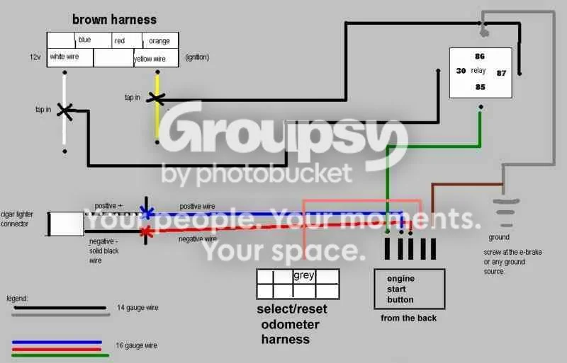
FIG. 2.8 -
Step 9: Mount the button, reassemble and test
Enlarge the hole behind the lighter position slightly so the button body and plug clear - do not overdo it. Apply double-sided tape to the mounting points, press the S2000 button into the modified lighter housing, and plug the floppy-drive connector into the back of the button, making sure the pins line up exactly as wired. Refit the stereo and dash fascia in reverse order of removal and reconnect the battery if it was disconnected. Test that the car still starts from the ignition switch (assuming that function was left enabled), then test the button: with the key turned to ON, press and hold the button until the engine starts, exactly as in an S2000. Note that with the ignition on at night the ENGINE START legend illuminates without the parking lights on - this is by design.
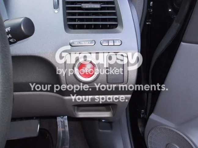
FIG. 2.9
- The button does not latch the starter - press and hold it until the engine fires, just like holding the key in START on a stock car.
- The relay schematic works on any car; the wire colors given are Honda-standard for the 5th-gen Prelude but must be verified with a test light on any other model before splicing.
- For a Civic FD, the engine start button and panel from a JDM Civic Type R bolt straight in with no modification and use the same wiring diagram (contributor report).
- A simpler two-wire variant (reported by a follow-up contributor for a DC2): connect one button wire to constant 12 V and the other to the starter wire at the ignition barrel loom - this keeps the key fully functional. S2000 buttons were found for about $50 on eBay versus about $160 from a dealer.
- Keep the factory ignition barrel. Replacing the barrel entirely with a button loses the steering lock and factory immobilizer and creates a serious theft risk, and would also require separate ACC and IGN switches.
Related procedures
All guides →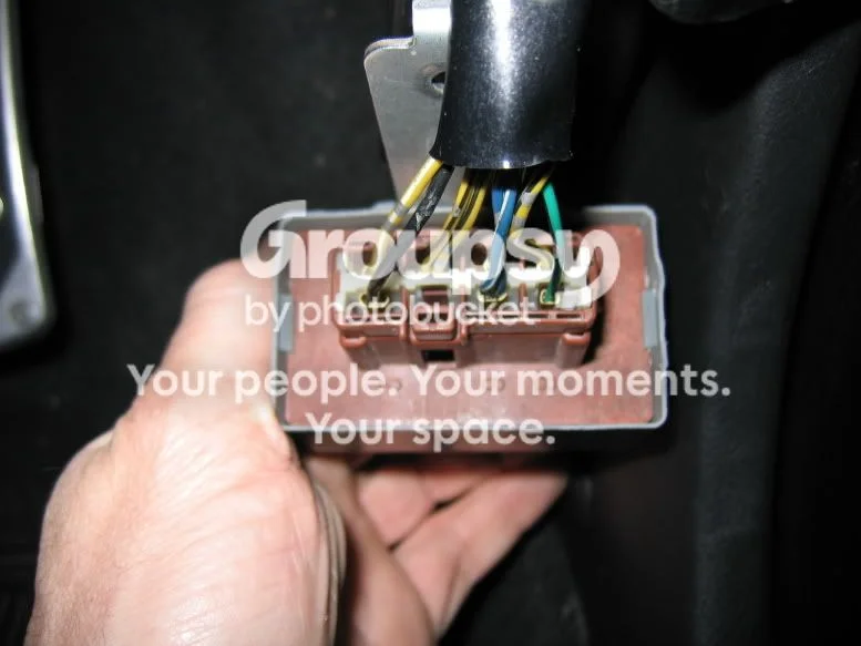
Tap right for next · left for back · Keys: ← → step · Space / PgUp / PgDn scroll · Esc exit