
Honda PGM-FI Fault Code Reading and ECU Reset (OBD0/OBD1/OBD2)
- Do not condemn and replace sensors on the code alone - misdiagnosis can leave you with an expensive, non-returnable part. Test the circuit first.
- Bridge only the 2-pin SCS connector. Never bridge the 3-pin DLC connector, and never short the 2-pin plug on OBD0 cars.
- Disconnecting the battery to reset the ECU wipes the radio security code - make sure you have the code before disconnecting.
Introduction
This procedure reads stored fault codes from the PGM-FI (Programmed Fuel Injection) engine control unit on Honda vehicles, letting you diagnose fuel injection and sensor faults without a scan tool. It covers AUDM code definitions, which also apply to JDM and USDM cars, and the codes are the same across OBD0, OBD1, OBD2a and OBD2b generations. On OBD0 cars the codes are read from a red LED visible through a window on the ECU itself; on OBD1 and OBD2 cars you bridge the SCS (service check) connector and read the codes as flashes of the yellow MIL (Malfunction Indicator Lamp, the check-engine light) on the dash. The procedure also covers resetting the ECU after repairs. Note the ECU can only report faults it monitors: problems with ignition leads, the coil, a blocked fuel or air filter, the main relay or the fuel pump will not set a code. Adapted from a community writeup by ECU-MAN on OzHonda (https://ozhonda.com/forum/showthread.php?67113-DIY-PGMFI-Diagnostics-Codes), including corrections from the follow-up discussion.
Procedure
10 steps-
Step 1: Identify your OBD generation
OBD0 cars (late 1980s to circa 1991) display codes directly on a red LED at the ECU - no connector bridging is required, and you should not short the 2-pin plug on these cars. OBD1 and OBD2 cars (1992 onward) require the SCS service check connector to be bridged before the MIL will flash codes. If you are unsure, locate the ECU: on OBD0 cars it has a small window with a red LED visible.
-
Step 2: Locate the SCS connector (OBD1/OBD2 cars)
The SCS connector is a blue 2-pin female connector, usually found with the blue 3-pin DLC connector in a green rubber holster near the ECU behind the passenger-side kick panel or glove box. Known locations from the thread: EG Civic - passenger side near the ECU (a single-wire plug near the driver-side hood release on an EG5 is for the fog lights, not the SCS); EK/EJ/EM Civic - behind the passenger kick panel or glove box (one EJ8 owner found it next to the fuse box, another behind the glove box); 96 EK1 sedan - soft green plastic plug hanging free above the ECU at the front passenger kick panel. It can blend into the wiring loom, so look carefully; you may need to remove the kick panel cover or glove box.
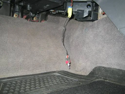
FIG. 2.2 -
Step 3: Bridge the SCS connector
Plug in a short connector, or bridge the two metal pins inside the blue 2-pin connector with a bent paperclip. Bridge only the 2-pin SCS connector - the 3-pin DLC next to it is for a scan tool and should not be connected to anything. A homemade short connector with an inline switch is handy if you also work on SRS and ABS systems.
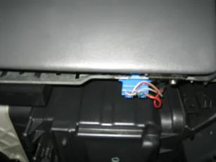
FIG. 2.3 -
Step 4: Turn the ignition to position II
Turn the ignition switch to position II without starting the engine. If the PGM-FI system has no stored faults, the MIL will stay on constantly with no flashing - this solid lamp with the SCS bridged is normal, not a fault. If there are stored codes, the MIL will begin flashing them.
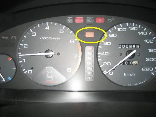
FIG. 2.4 -
Step 5: Read and record the flash sequence
Codes are flashed as follows: tens are long flashes, units are short quick flashes. Example - code 43 (fuel supply system) flashes as four long flashes followed by three quick ones. After a two-second pause the ECU repeats the code. If multiple codes are stored, each code is separated by a two-second pause. Write every code down and read the sequence through at least twice to be sure you have it right. Take care not to confuse similar codes: 1 versus 10, 2 versus 20, 20 versus 22.
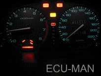
FIG. 2.5 -
Step 6: Cross-reference the fault code table
PGM-FI fault codes: code 0 ECU (electronic control unit), code 1 O2A (oxygen sensor 1), code 2 O2B (oxygen sensor 2), code 3 MAP (manifold absolute pressure sensor), code 4 CKP (crank position sensor), code 5 MAP, code 6 ECT (engine coolant temperature sensor), code 7 TPS (throttle position sensor), code 8 TDC (top dead centre sensor), code 9 CYP (cylinder position sensor), code 10 IAT (intake air temperature sensor), code 12 EGR (exhaust gas recirculation lift valve), code 13 BARO (atmospheric pressure sensor), code 14 EACV/IAC (electronic air control valve), code 15 IOS (ignition output signal), code 16 INJ (fuel injectors), code 17 VSS (vehicle speed sensor), code 19 ATLC (automatic transmission lockup control valve), code 20 ELD (electrical load detector), code 21 VTS (VTEC spool solenoid), code 22 VTP (VTEC pressure valve), code 23 KS (knock sensor), code 41 PO2H (primary oxygen sensor heater), code 42 SO2H (secondary oxygen sensor heater), code 43 FSS (fuel supply system).
-
Step 7: OBD0 cars: read the LED at the ECU
On OBD0 cars the ECU is usually under the passenger floorwell carpet. Pull the carpet back to expose the ECU; a hole in the case contains a red LED. Turn the ignition switch to position II and count the flashes exactly as described for the MIL. If the PGM-FI system is healthy, the LED gives a quick flicker at key-on and then stays off. Do not bridge the 2-pin connector on OBD0 cars, and read codes only from the ECU LED - the dash MIL does not blink codes on these cars.
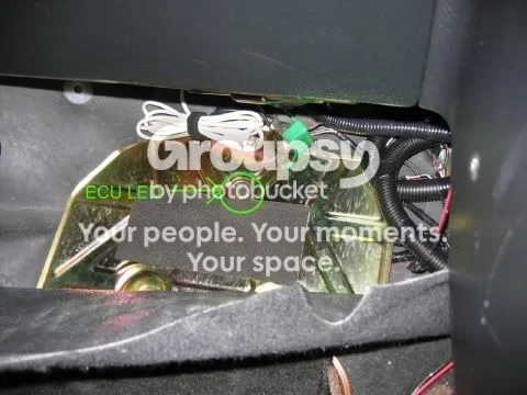
FIG. 2.7 -
Step 8: Diagnose and repair the faulty circuit
With the code identified, test the corresponding sensor or circuit before buying parts - a code indicates a circuit fault, not automatically a dead sensor. Remove the SCS bridge when finished reading. Remember the ECU cannot see ignition leads, coil, fuel filter, air filter, main relay or fuel pump problems, so a no-code condition does not rule those out.
-
Step 9: Reset the ECU
After repairs, clear the stored codes. On most OBD1 and OBD2 cars, pull the 7.5A BACKUP fuse in the under-hood fuse box for about 3 seconds - anything beyond 10 seconds is a waste of time. On the S2000, pull the 30A backup fuse in the under-hood box; on the 1988-89 second-generation CRX (OBD0), it is the fuse marked HAZARD. If you cannot find the fuse, disconnecting the negative battery terminal for 3-10 seconds also clears the memory, but you will lose the radio code, station presets and clock. Myths from the thread that you can ignore: leaving the fuse out for 10 minutes, or draining the ECU by touching battery leads together with the headlights on - all false.
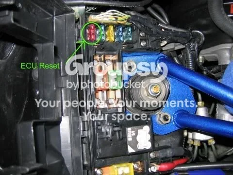
FIG. 2.9 -
Step 10: OBD2 cars: relearn the idle parameters
OBD0 and OBD1 cars are ready to drive immediately after a reset. OBD2 cars must relearn their idle load parameters: turn off every electrical accessory, start the engine and let it idle untouched until the radiator thermo fans cycle on and off at least twice, then switch off. There is no need to drive the car or rev it out - that is another myth.
- Later OBD2 vehicles (e.g. Integra) use an extended two-digit code set found in the replies: 45 system too rich/lean, 48 primary heated O2 sensor, 54 crankshaft speed fluctuation sensor, then 61 primary O2 circuit, 63/65 secondary O2 circuit, 67 catalyst system, code 70 automatic transaxle, codes 71-74 random misfire, 80 EGR, 86 coolant temperature circuit, 90 EVAP leak detected, 91 fuel tank pressure circuit, and 92 EVAP insufficient. Code 36 on a P30 ECU is traction control.
- EK1 models are OBD2 but do not use the standard OBD2a/OBD2b diagnostic connectors.
- If the CEL only flashes ABS codes when you bridge a connector, you have bridged the wrong plug - keep looking for the blue 2-pin SCS.
- Piggyback engine management (e.g. e-Manage) intercepting the VTEC solenoid wiring will set a false code 21 because the ECU no longer sees the solenoid's resistance; a 5W resistor from the VTEC wire to ground can satisfy the ECU.
- On an OBD0 car, a window LED that stays on constantly at ignition II usually indicates a dead ECU (or poor wiring on a rewired car).
Related procedures
All guides →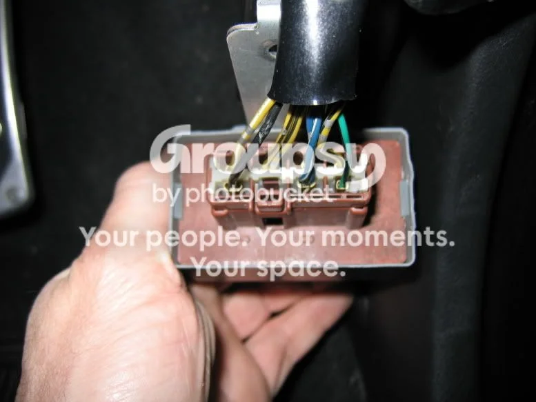
Tap right for next · left for back · Keys: ← → step · Space / PgUp / PgDn scroll · Esc exit