
OBD1 ECU (P75) and OBD1 distributor with OBD0-to-OBD1 conversion harness
into CR-X SiR (from Integra VTi-R)
Yes: the OBD1 ECU (P75) and OBD1 distributor with OBD0-to-OBD1 conversion harness from the Integra VTi-R fits the CR-X SiR (1989-1991) — moderate difficulty, modifications required.
Installation notes
Required modifications
The OBD1 ECU connects through an OBD0-to-OBD1 jumper harness (Boomslang Fabrications harness used) - no cutting of the car loom for the ECU itself. The harness sub-harness wires must be joined to the car: on an already-VTEC OBD0 car, the green (VTEC solenoid) wire goes to car-loom pin A8 (green/white) and the white (O2 signal) wire to C16 (white with silver dots), with optional VTP/heated-O2 wiring; on a non-VTEC chassis receiving a VTEC engine, the green, pink (IAB), red (knock) and four O2 wires are run directly to the engine-bay sensors, with the IAB solenoid's yellow/black wire fed from a switched 12 V source (available at the EACV). The distributor swap requires de-pinning the OBD0 connectors from the old distributor and transferring the OBD1 distributor wires into them per a specific pin map (ICM pin 7 to pin 7; OBD1 pins 1-6 to OBD0 pins 4, 3, 6, 5, 2, 1 respectively); the spade terminals on the power/tacho wires may need to be cut from the OBD0 distributor and soldered onto the OBD1 wires. Unused inputs (knock, ELD, O2 heater, VTP) are disabled in the ROM (Crome).
Important caveats
- Only works on OBD0 cars with non-vacuum-advance distributors; pre-OBD0 cars with vacuum-advance distributors share the same ECU connectors but are wired differently.
- If using a chipped P28 ECU, disable the knock sensor in Crome - the P28 does not use one.
- Mark the ICM wire (pin 7) before de-pinning the distributor connector so it is not confused with the other white wire, and note the orientation of the blue and black/yellow wires on the power/tacho connector.
- Get the firing order right (1-3-4-2) when refitting the leads.
Photos
1 fig.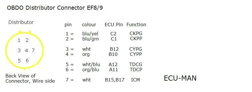
No guide yet — write one or browse all guides.
Reference
Done this swap?
Verify it and help the next builder.
Verified by 0 builders
Comments
(0)Sign in to join the discussion.
Please verify your email to post comments.
No comments yet. Be the first to share your experience.