
Honda Prelude (1992-1996) 4WS ECU Repair - Dry Solder Joint Reflow
- Disconnect the battery before removing the ECU - this must be done.
- Wear an anti-static wrist strap whenever handling the open ECU; static discharge can destroy the control electronics.
- The flexible ribbon joining the two PCBs (top left corner) is easily damaged - handle the boards carefully throughout the repair.
- Do not skip the steering full-lock calibration sequence after reassembly; the ECU will not set its 4WS parameters without it.
Introduction
The four-wheel steering (4WS) ECU in the 1992-1996 Honda Prelude (BB series) is a known failure point: high current through the relay and driver joints, combined with heat cycling, causes dry (cracked) solder joints over time. Symptoms include the 4WS warning light coming on intermittently while driving, on hot days, over bumps, or staying on permanently after the system previously worked. This repair pulls fault codes to confirm the ECU is the likely culprit, then removes the unit from behind the rear left seat, opens it, and reflows the suspect solder joints - typically fixing the system for the cost of a little solder. Codes in the 60s range are the common signature of this fault. This procedure will not fix faulty steering angle sensors, a faulty rear actuator (motor), misaligned sensors, or faulty wheel speed sensors, but if you are unsure why your 4WS is not working, it costs nothing to eliminate this common ECU problem first. The author reports the job takes about 45 minutes all up, but advises not to rush it. Adapted from a community writeup by ECU-MAN on OzHonda (https://ozhonda.com/forum/showthread.php?51150-DIY-92-96-Prelude-4WS-ECU-Repair), including corrections from the follow-up discussion.
Procedure
14 steps-
Step 1: Put the 4WS ECU into diagnostic mode via the SCS connector
Locate the blue SCS service connector in the driver's side footwell, behind the center console, and unplug it from its holder. Bridge its two terminals with the SCS service connector or a paper clip; this switches the 4WS ECU into diagnostic mode.
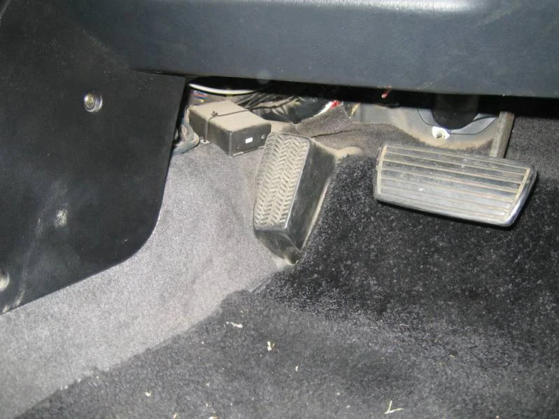
FIG. 2.1 -
Step 2: Read and record the fault codes
With the SCS connector bridged, turn the ignition to position II. The 4WS light comes on first, goes out, then starts flashing (if the check engine, ABS, and S4 lights also flash, ignore them for now and read them separately later). Count the flashes: long flashes are tens and short flashes are units, so seven long flashes followed by two short flashes is code 72. Be patient - after roughly two minutes of flashing the main codes from the first CPU, the 4WS light blinks rapidly for three seconds and then flashes the sub-codes from the secondary CPU. Write down every code and cross-reference them against a 4WS fault code chart. Codes in the 60s are the ones this repair commonly fixes.
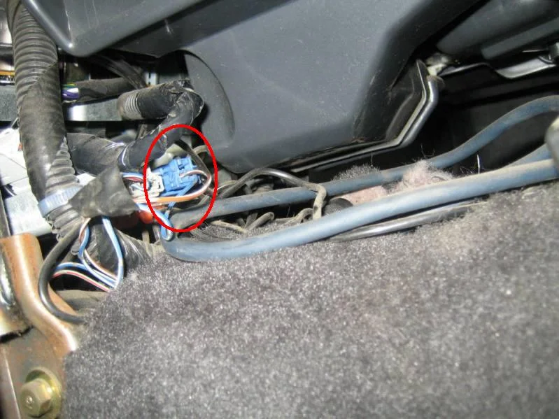
FIG. 2.2 -
Step 3: Reset the ECU and confirm the codes return
Reset the 4WS ECU, then take the car for a drive to see whether the ECU registers the same fault codes again. If the same codes return, proceed with the repair.
-
Step 4: Disconnect the battery
Disconnect the car battery before touching the ECU. This step is mandatory.
-
Step 5: Remove the rear left seat
The 4WS ECU lives behind the rear left seat. Remove the lower cushion first: lift the cushion at the release points and pull the lever while pushing down on the cushion. Then undo the two 10 mm bolts securing the seat back rest and lift it up and out.
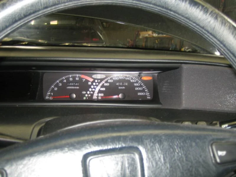
FIG. 2.5 -
Step 6: Unbolt the brackets and unplug the ECU
With the ECU exposed, remove the first bracket's bolts and move the bracket out of the way, then undo the remaining mounting bolts. One bracket bolt only needs to be loosened, not removed, to swing that bracket clear. Unclip the three wiring connectors that plug into the ECU.
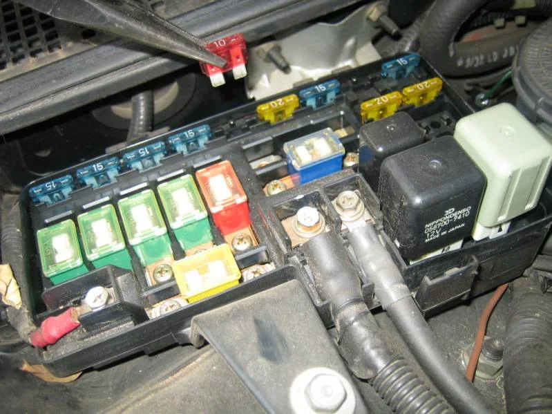
FIG. 2.6 -
Step 7: Free the ECU housing and remove it from the car
Remove the remaining mounting bolts (some only need loosening), pry open the black cover by pushing back its retaining tabs, undo the bolt behind it, and remove the four nuts securing the unit. Lift the complete 4WS ECU out of the car - it is a physically large unit.
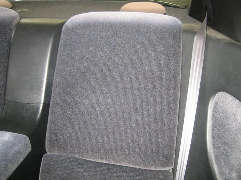
FIG. 2.7 -
Step 8: Open the ECU case (anti-static precautions)
Place the ECU on a workbench and put on an anti-static wrist strap before opening the case. Undo the case screws, then remove the screws holding the right-hand side's logic PCB. Be very careful not to damage the flexible ribbon (flex) in the top left corner that joins the two PCBs - it is fragile and must survive the whole job. Undo the screws on the left side of the ECU and lift out the metal plate.
-
Step 9: Remove the power PCB
Undo the screws securing the copper plates and lift the plates clear. Then undo the screws holding the relay and lift the relay aside. Remove the remaining PCB screws, then lift the power PCB out of the chassis, set it down on the bench, and flip it over to expose the solder side.
-
Step 10: Inspect all solder joints for dry joints
Examine the solder side of the board closely, using a magnifying glass if necessary. Dry joints show as a cracked ring around the pin or a dull, disturbed solder surface - but some bad joints look almost normal, so inspect every joint on both PCBs, not just the obvious ones.
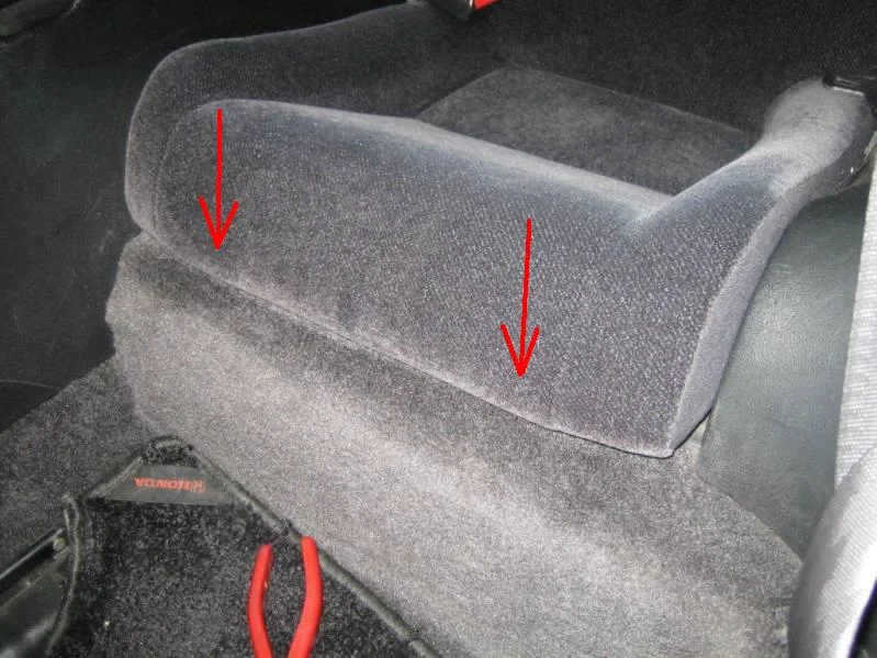
FIG. 2.10 -
Step 11: Reflow the suspect joints
With the soldering iron, reflow the solder on every bad joint. Check that solder has penetrated right through the PCB, but do not overdo it - excess heat or solder can damage the board. The relay and relay-connector joints are the common failure points: reflow them even if they look fine. Also reflow the driver transistor joints on the controller PCB, and fix anything else that looks suspect on either board.
-
Step 12: Reassemble the ECU
Reassemble the 4WS ECU in the reverse order of disassembly. Note that one screw is longer than the others - make sure it goes back in its original position.
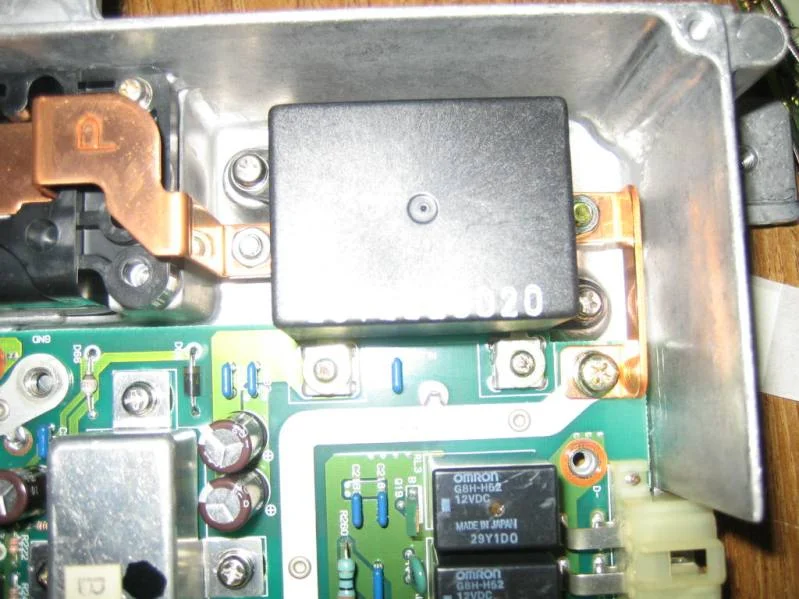
FIG. 2.12 -
Step 13: Reinstall the ECU and reconnect the battery
Refit the ECU into the car, bolt the brackets back in place, reconnect the three wiring connectors, reinstall the rear seat, and reconnect the battery.
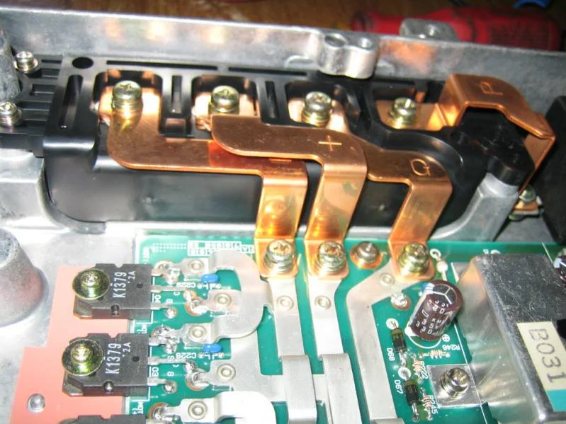
FIG. 2.13 -
Step 14: Recalibrate the 4WS system and test drive
Start the engine and wait for the 4WS light to extinguish. Then rotate the steering wheel to full lock left, full lock right, full lock left, full lock right, and back to center. This sequence is required - it sets the 4WS parameters in the ECU. Finally, test drive the car and confirm the system operates normally with no warning light.
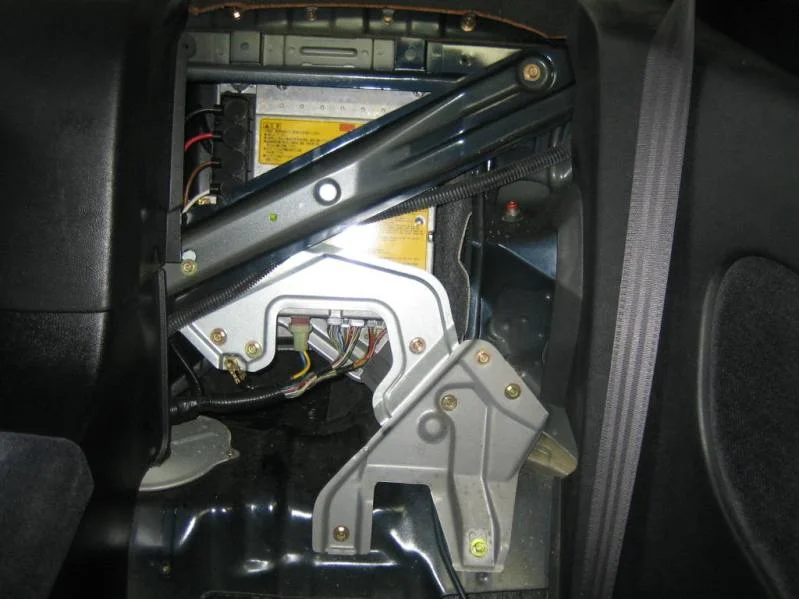
FIG. 2.14
- The high-current relay and relay-connector joints are the usual culprits - reflow them even if they look acceptable, since dry joints can be very subtle.
- The whole job takes about 45 minutes, but do not rush it; take as long as you need.
- A 4WS wheel alignment alone rarely fixes these symptoms, and can make things worse if the shop does not lock the rear actuator during the alignment - the 4WS sensors all need to be aligned correctly along with a good wheel alignment.
- This failure mode is normal aging: joints carrying high current heat-cycle and eventually crack regardless of original build quality, and reflowing them is a legitimate permanent fix - one owner reported the repair lasted years.
Related procedures
All guides →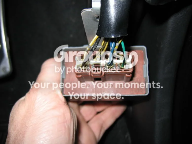
Tap right for next · left for back · Keys: ← → step · Space / PgUp / PgDn scroll · Esc exit