
Honda OBD0 to OBD1 ECU and Distributor Conversion
- This conversion only works on OBD0 cars with non-vacuum-advance distributors. Older pre-OBD0 cars with vacuum-advance distributors have the same ECU connectors but are wired differently and cannot use this procedure.
- Mark the ICM wire (pin 7) before de-pinning the distributor connector - it is easily confused with the other white wire.
- Get the firing order right (1-3-4-2) when refitting the leads, and take care with the pin orientation of the blue and black/yellow wires on the power/tacho connector.
Introduction
This conversion upgrades an OBD0 Honda to OBD1 engine management so it can run an OBD1 ECU, giving far more flexibility for tuning and engine-management options (for example chipped ECUs running Crome). The documented car is an OBD0 EF8 CR-X converted with a P75 ECU and an OBD1 distributor from an Integra VTi-R, using a Boomslang Fabrications OBD0-to-OBD1 jumper harness. Because the EF8 is already a VTEC car, only the VTEC solenoid and oxygen sensor wires needed connecting at the ECU end; the procedure also covers the extra engine-bay wiring needed when fitting a VTEC engine to a chassis that never came with VTEC. The distributor swap is handled by re-pinning the OBD1 distributor's wires into the original OBD0 connectors, so no donor loom plugs are required. The method applies to other harness brands, and the distributor section applies regardless of harness. Adapted from a community writeup by ECU-MAN on OzHonda (https://ozhonda.com/forum/showthread.php?64865-OBDO-to-OBDI-convertion), including corrections from the follow-up discussion.
Procedure
13 steps-
Step 1: Unplug the original OBD0 ECU
Remove the ECU cover and undo the four nuts holding down the large metal plate with a 10 mm socket. Unplug the three ECU connectors (A, B and C): firmly press the notch in the centre of each connector downwards and pull outwards at the same time. A flat-head screwdriver can be used to press the notch - be gentle.
-
Step 2: Plug in the conversion harness
Connect the OBD0-to-OBD1 conversion harness between the car's original ECU connectors and the new OBD1 ECU. The harness adapts the OBD0 A/B/C connectors to the OBD1 ECU plugs.
-
Step 3: Identify the sub-harness wires
The conversion harness includes an extra connector and loom (a sub-harness) of wires picked up on the OBD1 side that serve sensors in the engine bay: Green - VTEC solenoid; Pink - IAB, i.e. the secondary intake runners; Blue - the VTP switch (VTEC oil pressure); Red - knock sensor; Yellow - 12 V feed for the O2 heater; Orange - second O2 heater wire; Gray - ground for the O2 sensor; White - O2 signal wire. When the swap puts a VTEC engine into a chassis that was never VTEC-equipped, these wires go straight out to the engine-bay sensors (see the non-VTEC step). If you are converting a car that is already VTEC, the necessary circuits already reach the ECU connectors, so these wires are instead joined to the car loom near the ECU. In the documented EF8 only the VTEC solenoid and O2 signal needed wiring: the single-wire O2 sensor needs no heater wires, the VTP switch and knock sensor were disabled in the ROM (this ECU has no knock-sensor support), and the B16A has no IAB.
-
Step 4: Wire the sub-harness on an OBD0 VTEC car (EF8/EF9)
For an EF8/EF9 or any OBD0 VTEC car, join the sub-harness wires to the car loom at the ECU connectors: the Green wire joins the car loom at A8 (a green/white wire there), and the White wire joins the car loom at C16 (a white wire carrying silver dots). Optional, as written in the source: the blue wire can go to car-loom pin B5 (a blue/black wire) and the blue wire to car-loom pin B19 (a white wire with silver dots). If a 4-wire heated O2 sensor is fitted: the Yellow wire connects to one of the sensor's two black wires, the Orange wire takes the remaining black wire, the Gray wire mates with whichever sensor wire is green or gray, and the sensor's white (signal) wire reuses the existing car-harness O2 wire. Then skip ahead to removing the distributor.
-
Step 5: Wire the sub-harness on a non-VTEC chassis (VTEC engine installed)
For a VTEC engine going into a non-VTEC car, run the sub-harness wires directly into the engine bay: the Green wire goes out to the engine's VTEC spool solenoid; the Pink wire goes to the IAB solenoid valve's 2-pin connector, whose other (yellow/black) wire needs a switched 12 V feed (available at the EACV); the Red wire reaches the knock sensor sitting under the inlet manifold; the Yellow and Orange wires take the two black wires of the 4-wire O2 sensor (one each); the Gray wire picks up the sensor's green (or gray) wire; and the White wire pairs with that sensor's own white wire.
-
Step 6: Remove the OBD0 distributor
Unplug the two distributor connectors and the ignition leads, then undo the three bolts holding the distributor to the head and remove it. Place both the OBD0 and OBD1 distributors on a bench for the connector transfer.
-
Step 7: De-pin the connectors from the OBD0 distributor
Pay close attention here. Release the OBD0 connector from the OBD0 distributor's wiring: use a long pin to lift the retaining tab upwards while you tug the wire from the rear side of the connector. First mark the ICM wire (pin 7) so it cannot be confused with the other white wire, then remove all other pins until the OBD0 connector shell is free of the OBD0 distributor. Repeat the process on the power and tacho connector, and note which pin position the blue wire occupies and which one the black/yellow wire occupies.
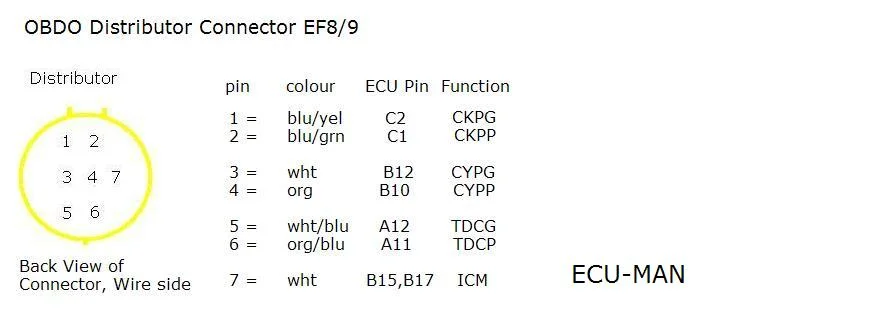
FIG. 2.7 -
Step 8: Transfer the OBD1 distributor wires into the OBD0 connector
Do not mix this step up. De-pin the OBD1 distributor connector one wire at a time, plugging each wire straight into the OBD0 connector shell as it comes free. Start by removing the white retainer inside the gray OBD1 connector - grab it with long-nose pliers and draw it out. Each pin releases when you push up and outwards on it with a long pin while facing the connector, helped by a gentle pull on the wire from behind. Transfer in this order: ICM wire from pin 7 of the OBD1 connector into pin 7 of the OBD0 connector; then OBD1 pin 1 into OBD0 pin 4; OBD1 pin 2 into OBD0 pin 3; OBD1 pin 3 into OBD0 pin 6; OBD1 pin 4 into OBD0 pin 5; OBD1 pin 5 into OBD0 pin 2; and OBD1 pin 6 into OBD0 pin 1.
-
Step 9: Swap the secondary connectors onto the OBD1 distributor
Swap over the remaining pair of connectors (power and tacho). De-pin them the same way. In this conversion the spade terminals on the OBD1 distributor wires were different and would not fit the OBD0 connector, so the spade terminals were cut from the OBD0 distributor wires and soldered onto the OBD1 distributor wires. Double-check the second connector is wired in the correct pin orientation noted earlier.
-
Step 10: Fit the OBD1 distributor
Bolt the OBD1 distributor to the engine, leaving the three bolts finger-tight so the ignition timing can be set later. Make sure the firing order is correct (1-3-4-2) when refitting the leads, or the engine will not run properly.
-
Step 11: Connect the OBD1 ECU and configure the ROM
Plug the OBD1 ECU into the conversion harness and confirm everything is connected. This car ran Crome with a stock 203 ROM for an OBD1 JDM B16A. Use Crome to disable any inputs the installation does not use - knock sensor, ELD, O2 heater and so on - so they do not throw fault codes.
-
Step 12: First start, warm-up and base timing
Now start the car - assuming the wiring is all correct, it should fire on the first attempt. Confirm the check engine light goes out once the engine starts and stays out while running (if it comes on, stop the engine and go to the fault-code step). Let the engine warm up fully; the thermo fans should cycle at least twice. Then locate the blue 2-pin connector that was originally the timing-set plug - it sits under the dash on the left-hand side, near the heater blower - and bridge it; with this harness that connector is now the SCS connector for OBD1 diagnostics and timing adjustment. Set the base ignition timing with a timing light, tighten the distributor bolts, recheck the timing, then remove the bridge from the SCS connector. Road test the car, confirm VTEC engages, and afterwards check the ECU again - there should be no stored codes.
-
Step 13: Diagnose fault codes if the check engine light stays on
If the check engine light comes on, or fails to extinguish, at ignition-on or after starting, something is likely miswired. Read the fault codes from the ECU: when this harness is fitted, the SCS connector duties are taken over by the old timing short connector - on an EF8/EF9 you will find it under the passenger floor well near the heater blower. Bridge that connector with a paper clip, then count the flash codes shown by the check engine light; they point to the miswired circuit. Rectify the problem and retest.
- Running a chipped P28 OBD1 ECU? Remember to disable the knock sensor in Crome, since no knock sensor is used by the P28.
- A single-wire O2 sensor works fine with the O2 heater disabled in the ROM; there is no need to buy a 4-wire sensor.
- A DC2 Integra OBD1 distributor bolted up and worked well on the B16A.
- Once you know the de-pinning technique, re-pinning the distributor connector only takes 5-10 minutes.
- If the ECU ROM is set up with the VTEC pressure switch disabled, the VTP wire does not need to be connected, although wiring it does no harm.
- A correctly wired conversion is expected to start on the first attempt - the author has seen the same result on a full B16A conversion.
Related procedures
All guides →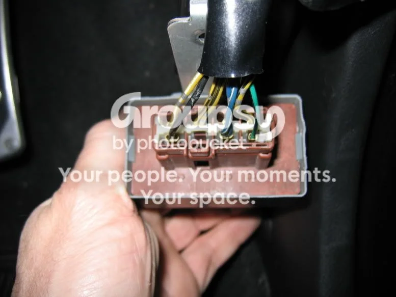
Tap right for next · left for back · Keys: ← → step · Space / PgUp / PgDn scroll · Esc exit