
EK Civic LED Instrument Cluster and Climate Control Conversion
- Acetone aggressively strips paint and plastic. Keep it strictly on the BACK of the gauge dials; any contact with the printed front face will peel the graphics off. Work in a ventilated area.
- Lever the hazard/demister switches and trim panels carefully; a bare flat-head screwdriver will scratch or dent the dash plastics.
- Test every LED for polarity before final reassembly to avoid tearing the dash down twice.
Introduction
This conversion replaces the dated amber incandescent dash lighting in the EK-series Honda Civic with LEDs throughout: the instrument cluster, climate control unit (backlight and button indicators), ashtray light, hazard and rear demister switches, and, on automatics, the gear position indicator. It covers the full dash disassembly needed to reach every bulb, the soldered 3 mm LED-plus-resistor conversions for the circuit-board-mounted indicator bulbs, and removal of the amber diffuser printed on the back of the gauge faces so any LED colour renders correctly. The finished result can be any colour scheme you like; the original build ran white gauges with red hazard/demister switches and blue climate control buttons. Adapted from a community writeup by TbM on OzHonda (https://ozhonda.com/forum/showthread.php?150689-Comprehensive-Ek-Civic-Led-Cluster-and-Climate-control-Conversion-*Updated-22-07-11*), including corrections from the follow-up discussion.
Procedure
10 steps-
Step 1: Remove the cluster surround and instrument cluster
Remove the screws from the upper dash trim and take off the two panels around the cluster to expose the cluster screws. Remove the four cluster screws and unplug the four connectors (manual cars may have three), then withdraw the cluster from the dash.
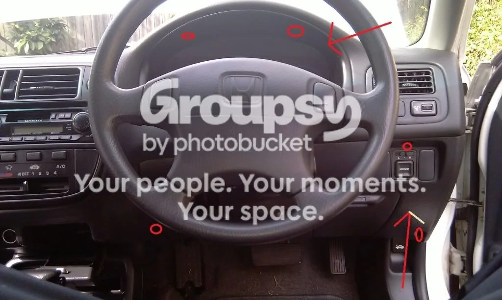
FIG. 2.1 -
Step 2: Remove the switches, glovebox, and lower panel
Lever the hazard and rear demister switches out of the dash from their outer edge using a trim removal tool (or a taped flat-head screwdriver, taking care not to scratch or dent the plastic), unplug them, and remove the glovebox. Remove the exposed screws, including a gold/brass screw hidden up inside the dash at the back of the A/C unit near the factory head unit screws; lie in the footwell and look up to find it. Pull the lower panel down, unclip the connector attached behind it, and remove the panel. The ashtray T5 bulb is accessible at this point.
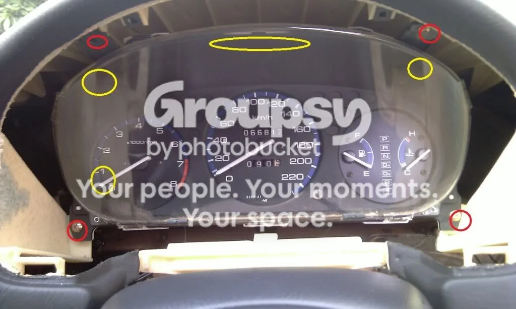
FIG. 2.2 -
Step 3: Release the heater cable and remove the head unit and centre section
Unclip the blue section of the heater control cable from its holder and pull the silver inner wire down to free it. Remove the head unit: the factory unit has two screws on its underside behind the A/C unit plus two connectors (aftermarket units per their own hardware). Behind it, unplug the clock connector and the two climate control connectors, then take out the entire centre section, climate control still attached. Removing two screws from the centre section's rear frees the climate control unit from the panel.
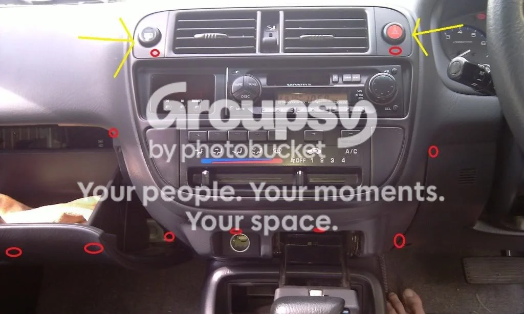
FIG. 2.3 -
Step 4: Disassemble the climate control and replace its backlight bulbs
Pop the buttons off the climate control unit with a flat-head screwdriver; each button has a small hole underneath into which the blade fits perfectly. Remove the five screws, lever the white clips up until the white section comes loose, then remove the final two screws. Replace the two T5 backlight bulbs (marked by the arrows in the original photos) with T5 LEDs.
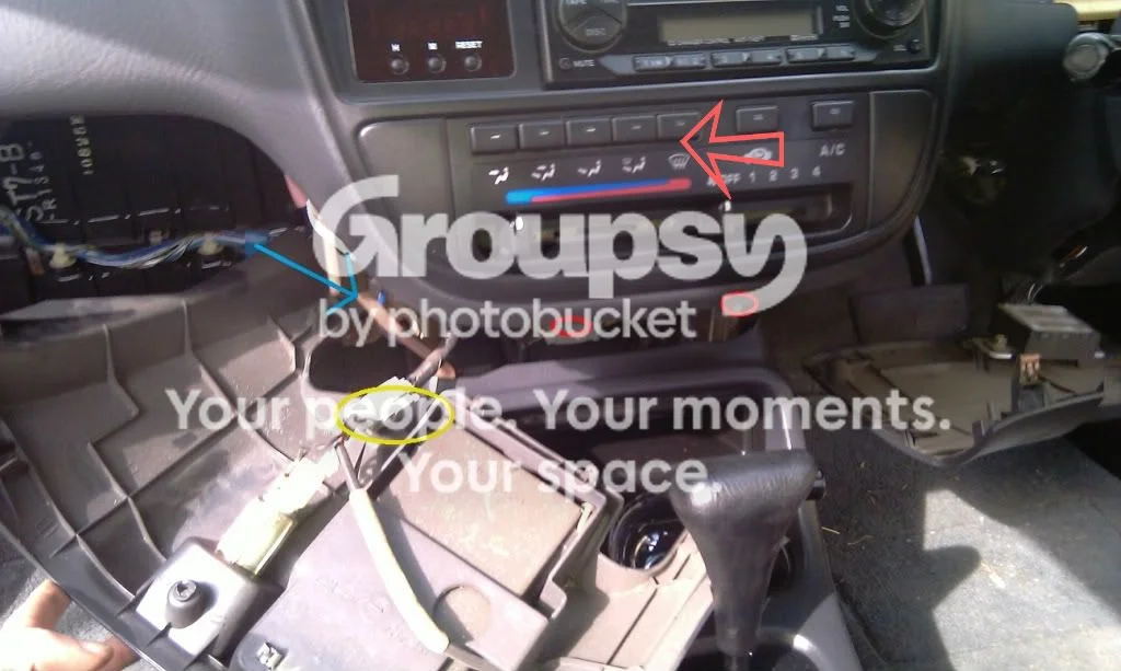
FIG. 2.4 -
Step 5: Solder the climate control button LEDs
Solder the seven new 3 mm LEDs into the climate control circuit board, observing polarity; the positive side is marked on the board. Keep the LED legs short: if an LED sits too tall, pressing the vent button can strike it and break the connection. Reassemble in reverse order, then plug the unit in and confirm every LED lights before screwing it back into the dash.
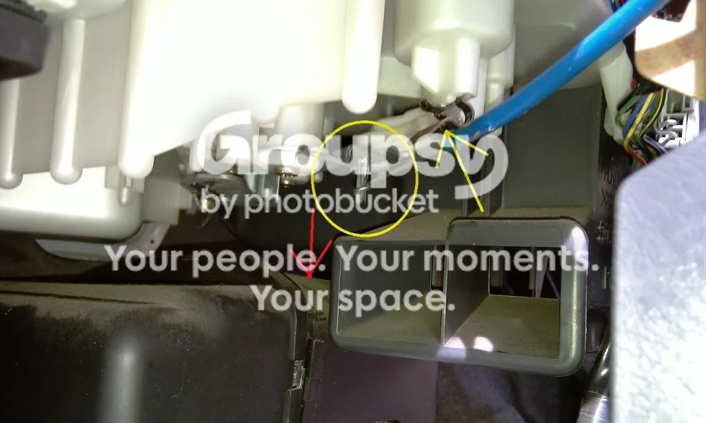
FIG. 2.5 -
Step 6: Open the cluster and swap the wedge bulbs
Undo the seven clips to remove the clear cover, then release the nine clips plus the left T5 bulb holder so the black covers come off, and switch those T5 bulbs to LEDs as you go. Flip the cluster over and change the remaining wedge bulbs: there are five backlight sockets (four T5 and one T10; the T10 holder can be modified to take a T5 by bending the contacts, so all LEDs match) plus two T5s along the top that illuminate the needles. On automatics, undo the additional clips to reach the screws and bulb behind the gear indicator. Remove the marked screws to free the gauges for the next step.
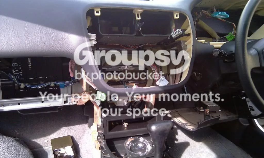
FIG. 2.6 -
Step 7: Remove the amber diffuser from the gauge faces (if fitted)
Shine a bright light through each gauge face. If the light comes through white, skip this step; if it comes through amber, the amber diffuser printed on the BACK of the dial must be removed or every LED colour will render amber. Dip cotton tips in a small bowl of acetone and work the back of each dial in quick, small back-and-forth strokes, keeping it wet, wiping excess with a rag. Doing just the outer band of each gauge and leaving the centre black works well and avoids removing the needles. Repeat for the speedometer and the fuel/temperature gauge; the fuel/temperature coating rubs off much more easily, so mostly use the rag there.
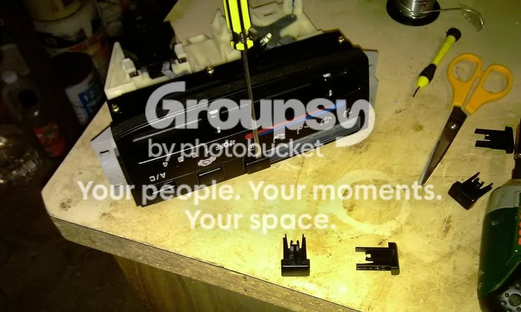
FIG. 2.7 -
Step 8: Convert the hazard and demister switch bulbs
Pull the bulb holders from the switches: the demister switch has two bulbs (the lower one backlights the symbol; the upper one lights when the switch is on) and the hazard switch has one. Remove each old bulb by straightening its wire and pulling it out. Fit a 3 mm LED into the holder (sanding the LED with 800-grit diffuses the light and helps it seat), wrap the shorter negative leg where the old bulb wire ran, then wire a resistor from the longer positive leg around to the other bulb-holder contact to complete the circuit. Solder the joints and trim excess wire. These switch bulbs are Neo Wedge type A (T3) if you prefer direct replacements.
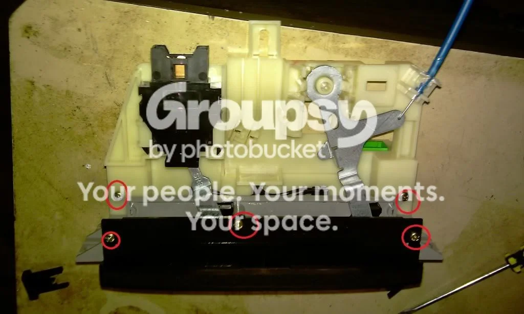
FIG. 2.8 -
Step 9: Convert the automatic gear indicator (automatics only)
To change the indicator colour from standard, carefully remove the coloured squares from the back of the indicator panel with acetone, one square at a time. If you removed the amber backing from the fuel/temperature gauge, mask the indicator outline with cut electrical tape to stop light leakage; foil and paper hot-glued inside the cluster can also reflect the cluster light away from the selector. Take each old bulb holder off the board, then convert all seven positions to 3 mm LEDs: run the short negative leg down one side and wrap it like the old bulb wire, pierce the positive leg through the side of the holder, wire it to a resistor, wrap the resistor's other end where the stock wire ran, and solder everything.
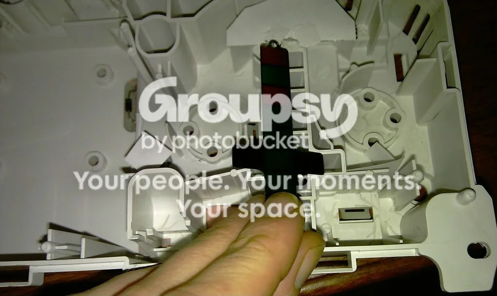
FIG. 2.9 -
Step 10: Test everything, then reassemble the dash
LEDs are polarised: before final assembly, plug in the cluster, climate control, and switches and confirm every LED lights. If a socketed LED stays dark, rotate the bulb or its holder 180 degrees; if a soldered LED stays dark, re-check the joint and polarity. Once everything works, reassemble the dash by following the disassembly steps in reverse.
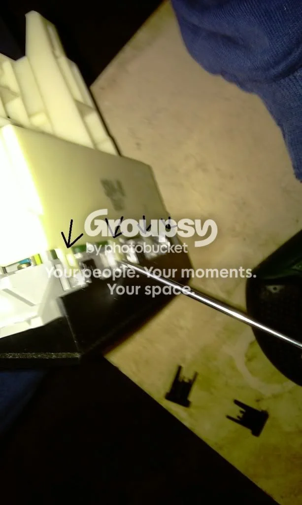
FIG. 2.10
- Use 360-degree wedge LEDs in the cluster; basic single-face T5 LEDs leave very bright and very dark patches. Hot spots can be eliminated by hot-gluing a small foil-and-paper cap on top of each LED so the gauges are lit by reflected rather than direct light.
- One T5 LED can be used in the T10 socket if you bend the bulb holder's contacts, keeping the backlight colour and intensity uniform.
- Brightness tuning: a lower-value resistor makes an LED brighter; a higher-value resistor or light sanding dims/diffuses it. Aim for matched brightness across all switches.
- The 3 mm LEDs behind the climate control buttons have room to spare; 5 mm LEDs also fit if that is what you have.
- The hazard/demister switch bulbs are Neo Wedge type A (T3) if you want plug-in replacements instead of soldered LEDs.
- Cluster socket map: four T5 plus one T10 for the gauge backlight, and two T5s at the top for needle illumination.
Related procedures
All guides →
Tap right for next · left for back · Keys: ← → step · Space / PgUp / PgDn scroll · Esc exit