
Honda Valve Clearance (Tappet) Adjustment
- The engine must be stone cold. Adjusting clearances on a warm engine will give incorrect settings.
- Do not mix up the intake and exhaust clearance specifications - they are different.
- DO NOT forget to remove the socket and breaker bar from the crankshaft pulley before starting the engine.
- Do not overtighten the tappet locknuts (they can snap) and never leave them loose - either mistake can wreck the valvetrain.
- If you jack the car up for access to the crank pulley, always support it on jack stands.
Introduction
Valve clearance (tappet or valve lash) adjustment restores the specified gap in the valvetrain, quieting the characteristic Honda tappet tick and protecting the rocker arms, valves, and camshaft from accelerated wear. Excessive lash left uncorrected can eventually damage a rocker arm, valve head, or camshaft. The procedure applies to virtually all Honda engines with screw-type tappet adjusters, SOHC and DOHC alike (D-series, B-series, H-series, F-series, from Civic to NSX); the exceptions are the C-series 2.5L and 2.7L Legend engines, which use hydraulic lifters on the intake side. The original author recommends checking clearances every 20,000 km. The engine must be stone cold (left overnight or at least several hours), and you must have the correct intake and exhaust clearance specifications for your exact engine before starting; there are no separate hot specifications for these engines. On SOHC engines the clearance is measured between the adjusting screw and the valve tip; on DOHC engines it is measured between the camshaft lobe and the rocker arm. Adapted from a community writeup by ECU-MAN on OzHonda (https://ozhonda.com/forum/showthread.php?15443-DIY-tappet-adjustment), including corrections from the follow-up discussion.
Procedure
10 steps-
Step 1: Confirm clearance specifications and let the engine cool overnight
Obtain the intake and exhaust clearance specifications for your exact engine and do not mix them up. Examples quoted in the discussion (all cold): B16A and all DOHC VTEC B-series including B18C variants - intake 0.15-0.19 mm, exhaust 0.17-0.21 mm, measured at the camshaft; B18B - intake 0.003-0.005" (0.08-0.12 mm), exhaust 0.006-0.008" (0.16-0.20 mm), measured at the camshaft; H22A1 - intake 0.15-0.19 mm, exhaust 0.17-0.21 mm; D15B7 - intake 0.18-0.22 mm, exhaust 0.23-0.27 mm, measured at the valve. The engine must be stone cold - leave it unstarted for several hours, ideally overnight. Do not attempt the job without the correct specifications, the correct tools, and a clear understanding of the whole procedure.
-
Step 2: Remove the rocker cover
Unplug the spark plug leads and disconnect the PCV tube from the rocker cover. Undo the five rocker cover bolts and lift the cover off. Optionally remove the spark plugs as well - this greatly reduces the effort needed to turn the engine over by hand.
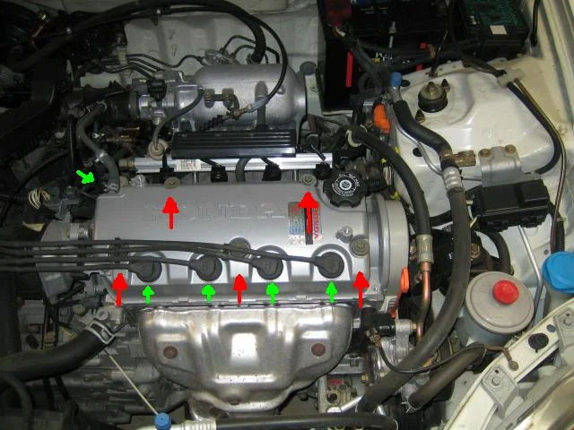
FIG. 2.2 -
Step 3: Remove the upper timing belt cover
Undo the two 10mm bolts securing the upper timing (cam) belt cover and remove the cover so you can see the camshaft sprocket markings.
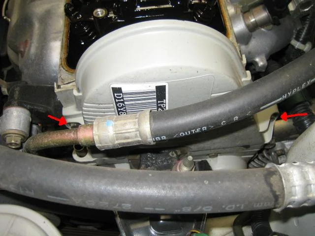
FIG. 2.3 -
Step 4: Fit a breaker bar to the crankshaft pulley bolt
Fit a 17mm socket to a long 1/2" bar, connect a breaker bar, and fit it to the harmonic balancer (crankshaft pulley) bolt. You can reach it through the inner guard without removing anything: either jack up the front of the car, support it on jack stands and remove the wheel, or keep the car on the ground with the steering turned to full left lock for access.
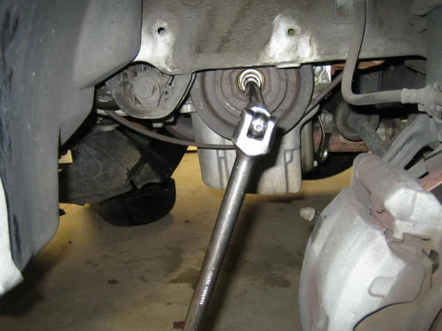
FIG. 2.4 -
Step 5: Set cylinder 1 to top dead centre
Turn the engine over counter-clockwise with the breaker bar until the UP mark on the cam sprocket points up and the TDC mark on the harmonic balancer lines up with the pointer on the timing cover. The TDC mark is the single (usually white) mark on the circumference of the larger ring of the balancer; the ignition timing mark is a red one sitting between two other marks - do not confuse them. At TDC on the compression stroke for cylinder 1, the cam sprocket markings also align with the cylinder head's flat surface. Confirm cylinder 1 is on its adjustable stroke by lifting the tops of its tappets - they should move up and down slightly.
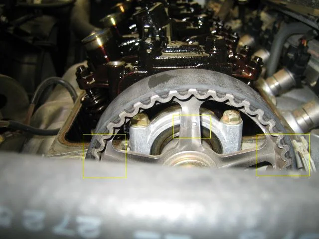
FIG. 2.5 -
Step 6: Measure the clearance on cylinder 1
Insert the correct feeler gauge for your specification between the adjusting screw and valve tip (SOHC) or between the camshaft lobe and rocker arm (DOHC). Push and pull the gauge a few times to get a feel for the clearance: it should feel snug - the gauge should slide out with slight resistance, neither jammed tight nor loose. On DOHC engines the original author inserts the gauge from the outside of the head and then re-checks from the inside to make sure the setting is not too tight.
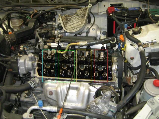
FIG. 2.6 -
Step 7: Adjust the exhaust and intake tappets on cylinder 1
Place the 10mm ring spanner on the tappet locknut with the feeler gauge in position and a flat-blade screwdriver on the adjusting screw. Crack the locknut just enough that the screw can turn. Turn the screwdriver counter-clockwise to increase (loosen) the clearance or clockwise to reduce (tighten) it. Make an adjustment, hold the screwdriver firmly so the screw cannot move, and nip up the locknut - snug enough that nothing moves, but not fully tight. Re-check the clearance and repeat until it is correct; expect up to 10 attempts at first, dropping to 3 or fewer with practice. When the clearance is right, hold the screwdriver firm and tighten the locknut properly - do not overtighten it (it will snap) and do not leave it loose (the adjustment will drift and can damage the valvetrain). Check the clearance one final time, then repeat for the other exhaust valve, then the intake valves (remember the intake specification is different). Before moving on, confirm all four locknuts on the cylinder are tight and re-check each clearance once more.
-
Step 8: Rotate the crank and adjust the remaining cylinders in firing order 1-3-4-2
Turn the crankshaft 180 degrees counter-clockwise (the cam sprocket turns 90 degrees - the original post initially said 90 degrees at the crank and was corrected in the replies). Check the cam sprocket markings, then adjust cylinder 3 intake and exhaust exactly as for cylinder 1. Turn the crank a further 180 degrees counter-clockwise so the balancer TDC mark lines up again, and adjust cylinder 4. Turn a final 180 degrees counter-clockwise (sprocket markings as they were for cylinder 3) and adjust cylinder 2. As a sanity check, the tappets of the next cylinder in the sequence should feel slightly loose when that cylinder reaches its adjustment position.
-
Step 9: Refit the covers
Refit the upper timing belt cover and tighten its two 10mm bolts. Clean the head surface where the rocker cover gasket sits and clean the gasket itself on the cover. Apply Ultra Grey (or Hondabond) to the gasket, concentrating on the corners, the cam seal area and around the distributor - these spots leak most readily. Refit the rocker cover and torque the bolts to the manufacturer's specification in a criss-cross pattern. Tighten the spark plugs if you loosened them, and reconnect the leads and PCV tube.
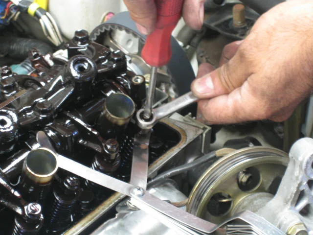
FIG. 2.9 -
Step 10: Remove the breaker bar and start the engine
Before starting, remove the socket and breaker bar from the harmonic balancer bolt - a forgotten bar will spin with the crank and tear the front guard open. There is no need to let the sealant cure: refit the cover and start the engine. The valvetrain should be noticeably quieter.
- Access on DOHC VTEC heads is tight. Cheap workaround from the replies: a 10mm tube socket (about $12) lets you pass the screwdriver through its centre while turning the nut with a spanner on the other end - it duplicates the expensive factory tappet tool. A 10mm brake-bleed spanner also fits the confined space, or use a 10mm socket on an extension bar.
- Feeler gauge feel: aim for the gauge to slide out with a little resistance, not so tight that it needs real force. One approach from the replies: set to the middle of the range (e.g. 0.004" on a 0.003-0.005" spec) so it grips, then confirm the lower value still slides in easily.
- The clearances must be set with the engine stone cold - there are no separate hot specifications for these engines.
- A rocker cover gasket in good condition can be reused many times with a smear of sealant; only replace it if it is cracked or hardened. Gaskets typically last well over 80,000 km.
- Hearing air escaping as you turn the crankshaft by hand is normal (cylinders compressing).
- If the ticking returns a week after adjustment, the locknuts were probably not tightened enough and the settings have drifted - re-do the adjustment rather than just re-tightening the nuts.
Related procedures
All guides →
Tap right for next · left for back · Keys: ← → step · Space / PgUp / PgDn scroll · Esc exit